5
$\begingroup$

I am coming to this with an amateur understanding of CL, Cp and their contribution to the overall lift of a wing, so bear with me :)

I have been wondering for some time about whether you could design a system of slats (perhaps multiple stages of them) that deploy in tandem with flaps as to prevent the nose down pitch moment experienced on a typical wing when flaps are deployed. The idea is to bring the leading edge of the wing forwards and down, to extend the overall chord length, and in turn bring the relative aoa back to what it was before, but with a much higher cl-max (and of course lots of drag)?

The main idea behind this is that it would be very useful for canard aircraft if deployed on both the main wing and the canard. In theory it could greatly reduce the minimum speed and distance for takeoff without changing the lift ratios or messing with the cl/cg relationship. It seems like an elegant solution and I am puzzled as to why no one has done it yet? Am I missing something?

I apologise if this doesn't make sense. As I say, I'm still getting to grips with the concepts.

$\endgroup$
1
  • 2
    $\begingroup$ "I am puzzled as to why no one has done it yet? Am I missing something?" What you seem to be missing is that every major jet airliner has both leading edge slats and trailing edge flaps. So yes... it has been done, often and successfully. (unless I'm missing something in your question?!) $\endgroup$ Commented Jul 8 at 3:31

6 Answers 6

4
$\begingroup$

I have been wondering for some time about whether you could design a system of slats that deploy... to prevent the nose down pitch moment. The idea is to bring the relative aoa back to what it was before.

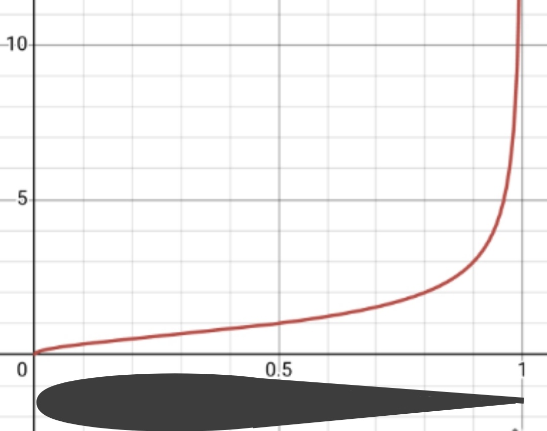
The main purpose of a leading edge and/or trailing edge device is to change the camber of the airfoil. Without entering in physical/mathematical details, it can be shown that, going from the leading edge toward the trailing edge of an airfoil, the contribution of each piece of its camber to the aerodynamic force is proportional to the following plot/equation (my own plot of the function $\sqrt{\frac{x}{1-x}}$):

enter image description here

There it can be seen that the contribution to the aerodynamic forces of the forward part of the camber is basically negligible while it is the 30-something% most rearward portion of it which almost entirely contributes to the aerodynamic forces.

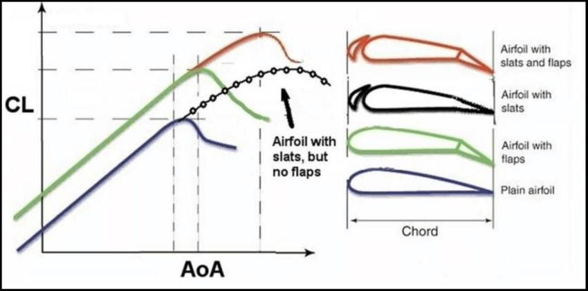
This explains why spoilers, ailerons, rudders, ... whatever surface used to change the aerodynamic forces is placed toward the end of the airfoil and not at its leading edge. This also tells us that any leading edge device like slats does not alter significantly the aerodynamic forces: slats are indeed used to improve/extend stall characteristics at high AoA but have almost no impact on the (slope of the) lift or on the pitching moment (source):

enter image description here

The main idea behind this is that it would be very useful for canard aircraft if deployed on both the main wing and the canard

In a lifting-canard configuration, flaps are only sparingly (or even not at all) used on the main wing because in a lifting-canard configuration the main wing normally lies quite backward and therefore any aerodynamic force created there possesses a big leverarm in respect to the CG: using powerful flaps on the wing would create a lot of pitching moment which should be counteracted by the canard which would then need to be designed bigger/heavier/draggier i.e. the opposite of why a canard design had been chosen in the first place. This is why in a lifting-canard configuration flaps are normally placed only on the canard itself and with fancy constructions.

$\endgroup$
5
  • $\begingroup$ Do you have a source for the image? Maybe I'm misinterpreting, but it looks opposite to the force distribution I normally see for example in this answer $\endgroup$
    – ROIMaison
    Commented Jul 8 at 11:32
  • $\begingroup$ @ROIMaison: the picture is my own work of the function $\sqrt{\frac{x}{1-x}}$ made under desmos.com. That function gives the lift due to camber for the thin airfoil theory, it can be found in any aerodynamics book I suppose, I'm quite sure that Mark Drela cover it in his book. $\endgroup$
    – sophit
    Commented Jul 8 at 11:46
  • $\begingroup$ I'm still confused if I understand the plot. Is it the distribution of lift over the chord? Then I don't think it's correct, most of the curvature is at the front, so I expect most of the forces to be located there. This also matches airfoil pressure plots at 0 deg; like this $\endgroup$
    – ROIMaison
    Commented Jul 8 at 12:15
  • 1
    $\begingroup$ @ROIMaison: I've checked - Mark Drela gives a slightly different equation than the one that I wrote for the contribution of the camber, i.e.: $C_{l_0} = 2 \int_{0}^{\pi} \frac{dZ}{dx}(cos\theta -1)\, d\theta$. Here $\frac{dZ}{dx}$ is the slope of the main chord (aka the camber) and the weighting function is $(cos\theta -1)$ which, between $0$ and $\pi$, has a similar influence of what I've plotted in my answer. $\endgroup$
    – sophit
    Commented Jul 8 at 12:43
  • $\begingroup$ Thanks for the explanation and reference! I found the relevant text and will check. I think it the plot is too much of a simplification to drive the explanation. The moment any angle of attack is added, the lift distribution over the chord looks very different. $\endgroup$
    – ROIMaison
    Commented Jul 8 at 13:04
2
$\begingroup$

Flap pitching moments are normally nose down with extension, although some airplanes pitch up with flap because nose-up trim changes from increased downwash on the tail overpower the nose-down trim changes from the main wing's camber change and aft pressure distribution shift with flap extension.

In sailplanes with flaps, this nose-down with flap extension dominates because the flaps have minimal trim change influence on the T tail of the glider from downwash, and the effects apparent to the pilot net out as nose down pitching moment effects on the main wing. So flaps down pitches the nose down, and flaps up (including reflexed above neutral for high speeds) the opposite.

Anyway, in canard-land, the Beech Starship got around the pitching moment changes from flap extension by variable sweep of the canard, about the most elegant way to deal with the problem, and alternatives using compensating aerodynamic surfaces on the wings sound like a lot more complexity than needed. As it was, the Starship was such a train wreck it nearly bankrupted Beechcraft.

Rutan's homebuilt canard designs didn't use flaps, largely to avoid having to use a variable sweep canard surface, a bit much for such homebuilt, and only have a speed brake under the fuselage. They are definitely not STOL airplanes.

And that's the rub, and the reason the configuration is so rare. The canard concept, like the flying wing, is an aviation dead end as anything more than a specialty configuration, with more negatives than positives outside of very specialized uses.

$\endgroup$
1
$\begingroup$

Right at the moment when flaps are deployed, we actually experience a nose up movement, at least in the planes that I've flown so far.

Anyway...

Remember that drag is a side effect whenever we want to generate lift so if you now don't increase the lift (by increasing any combination of thrust and AoA) then, yes, the plane will eventually lower its nose (more than you'd want it to).

However, flaps also change the camber so my understanding is that if the CoP is not shifted, the "new airfoil" might not sustain itself like the previous one, so you have to have the CoP shift - because the CoG is shifting too. Flaps have weight so when they stick out of the wing, the CoG shifts a bit rearward.

The positions of the CoP and CoG with respect to each other affect the pitch of the aircraft (and therefore also the AoA), so if one moves the other might need to too. Not saying that their relative positions should be the same but you need to be able to shift the CoP w.r.t. the CoG. Forcing the CoP to retain its original position doesn't really help- you need to make adjustments depending on what you want anyway. Flaps usually go out more than slats, so the net weight shift is towards the aft.

So far, the above is only with respect to non canard aircraft.

Looking forward to more answers by other people as well.

$\endgroup$
1
$\begingroup$

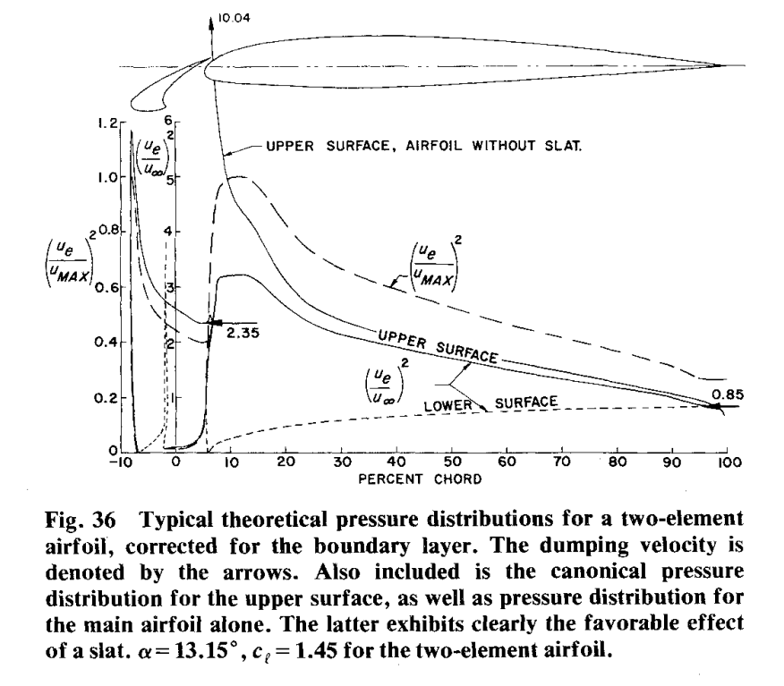
Do not focus on the slat alone, you have to keep the whole system in mind. Slats generate lift ahead of the c.o.g., but they also deflect the air downwards (Dumping velocity). The incoming air thus hits the wing-element at a lower (or negative) effective angle of attack, thereby reducing the suction peak and delaying stall.

Look at this image from A.M.O. Smith's paper "High lift Aerodynamics", a highly recommended paper if you want to learn about the workings of high lift devices.

Velocity distribution of airfoil with slat

Several things are happening:

  • Lift generated by the slat (reduces pitch down moment)
  • Suction peak of the wing gets reduced (increases pitch down moment, as there is less lift ahead of the C.O.G)
  • Lift of the wing gets reduced (depends on exact effects)

The net moment delivered by the slat is influenced by its effect on the lift distribution of the wing, and therefore rather limited.

$\endgroup$
1
$\begingroup$

There are two answers to what you are asking, here:

Slats are not used for this, as slats have very little effect on coefficient of moment. There is no aircraft (that I'm aware of, at least) which uses slats for control forces in general, nevermind for trimming centre of lift. Their use is in enhancing overall lift force by preventing stall rather than being a lifting or control device in themselves.

This makes sense even just from the rule-of-thumb of a wing's aerodynamic chord line being 25% from the leading edge; even if leading and trailing edge surfaces produce the same forces when deflected the same, a trailing edge surface will produce several times more torque, and therefore provide the desired control with a fraction of the structure and machinery.

Flaps however, are used for this, though not commonly. The A350 is the main and most prominent example; rather than performing cruise trim with fuel movement, as the A330, A340, and A380 (and Concorde) do in order to minimise trim drag, the A350 can adjust the retracted position of its flaps.

Using a combination of trimming flaps, the horizontal stabiliser angle, and elevator angle, it is able to achieve comparable cruise efficiency with suboptimal centre of gravity as the older aircraft are, without needing the extra fuel tanks and pumps, and the reliability concerns they present.

The fuel movement system likely is superior in absolute performance, but weight and reliability savings presented mean that Airbus did not continue the system in their newest design.

You can find some airliner nerds discussing the switch here.

$\endgroup$
2
  • $\begingroup$ +1 for the link to the nerds' conversation! And, welcome to Av.SE. $\endgroup$
    – Ralph J
    Commented Jul 16 at 16:27
  • $\begingroup$ The 787 had the variable camber system first, eliminating the trim tank. The A350, and 777X then got it later. $\endgroup$
    – user71659
    Commented Jul 16 at 18:27
0
$\begingroup$

The answer is yes, slats can be and commonly are combined with flaps to produce essentially a high lift cambered wing, ideal to reduce airspeed required for lift by increasing coefficient of lift.

The slats can help maintain center of pressure in the wing but ...

there is also the effect of changing wing configuration on the airflow over the tail to consider.

Cessna ingeniously added this effect in its simple flap design of the 172 model. While extending flaps will shift wing Cp rearwards, it also increases downwash on the tail. With its much longer lever arm, the net torque effect (around the center of gravity) is a pitch up.

As pitch is a result of aerodynamic forces, a variety of factors can affect it.

$\endgroup$

You must log in to answer this question.

Not the answer you're looking for? Browse other questions tagged .