3
$\begingroup$

I just purchased a used altimeter from eBay because it'll look pretty on a shelf, and I may add a computer interface to it. However, I need help finding information on it.

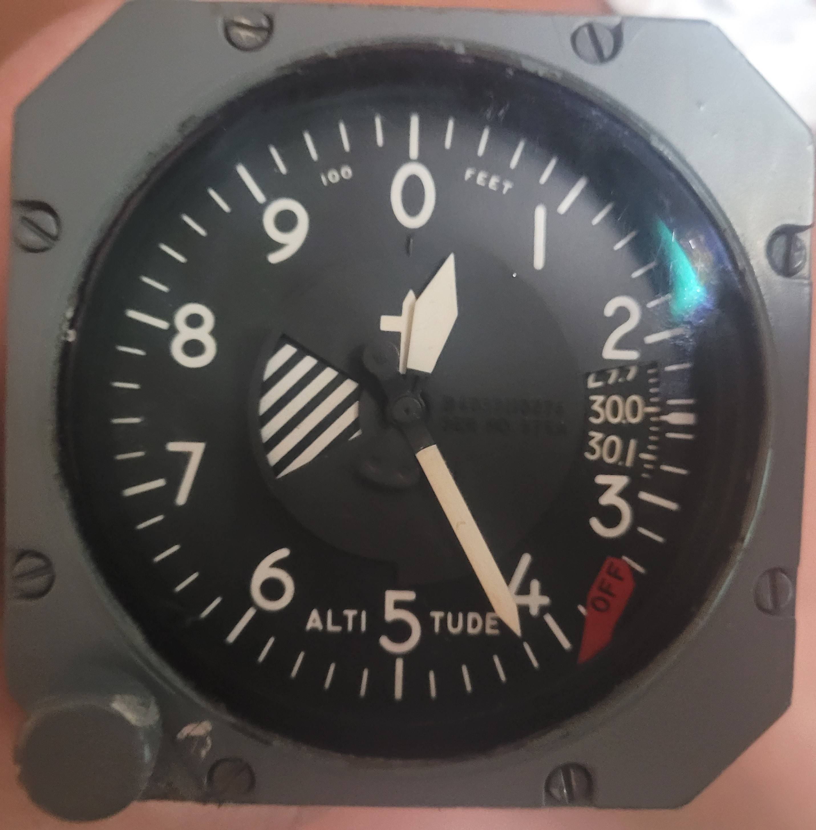
This (from what I've been able to gather) is a Kollsman Instruments model B40331-10-276 altimeter. It's serial number 575A. There is a port on the back with a red plastic plug, which is obviously the static pressure connection (NB: If I try real hard I can suck myself up to 8000 feet). There is also what I would call a "cannon plug" with 19 pins.

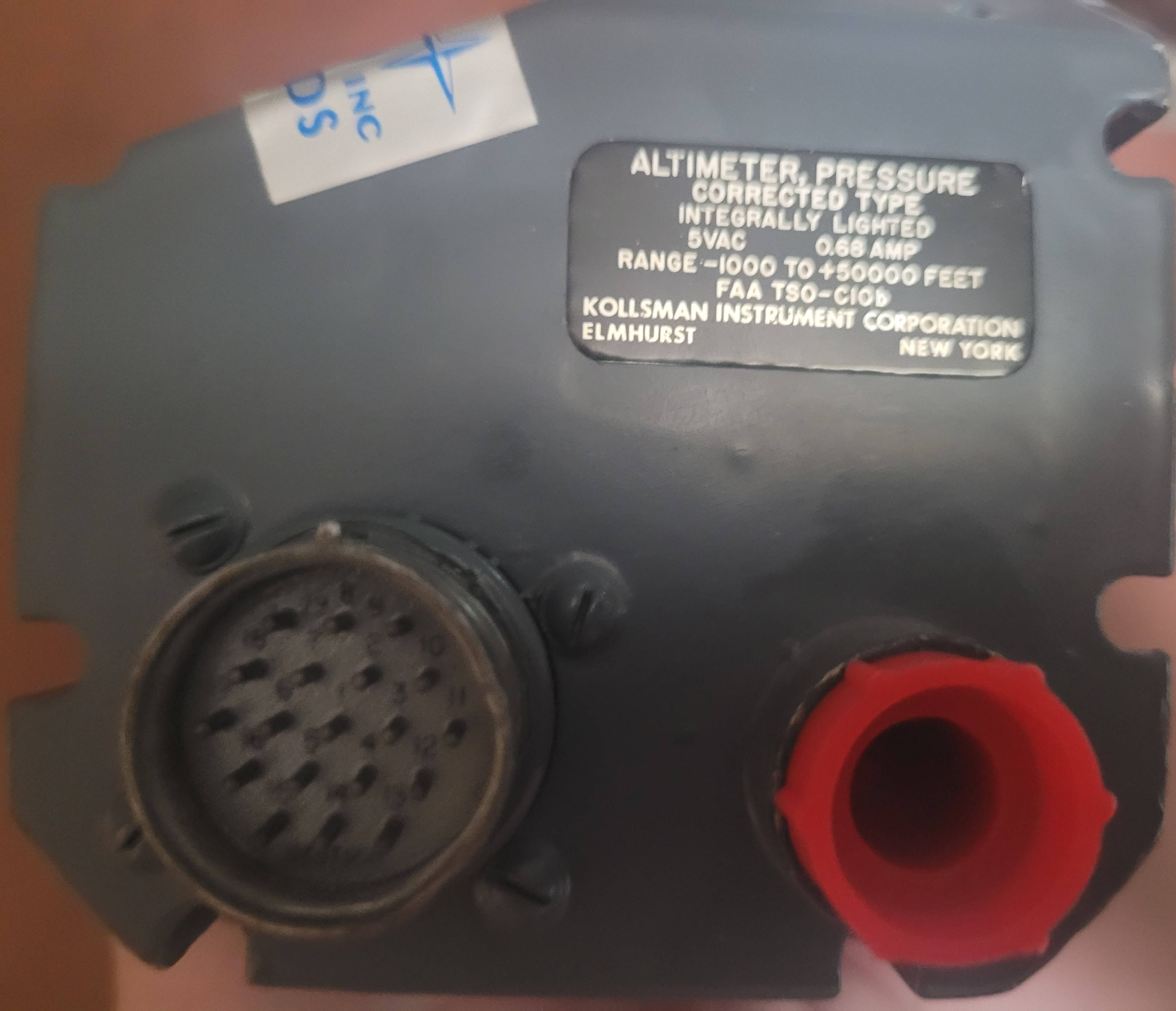
Label on the back reads:

ALTIMETER, PRESSURE CORRECTED TYPE INTEGRALLY LIGHTED 5VAC 0.68 AMP RANGE -1000 to +50000 FEET FAA TSO-C10b KOLLSMAN INSTRUMENT CORPORATION ELMHURST NEW YORK

Primarily, I want to know the specification of that electrical port - pinout, voltage/current ratings, protocol descriptions, etc. A bonus would be a repair/calibration manual with all the details. Perhaps this is a standard avionics connector, so a link to a standard would work.

Of course, if this is identical in all respects to another model, and there is information on that model, please share.

What are the dimensions of the threaded static port as well?

Here are some photos of the instrument:
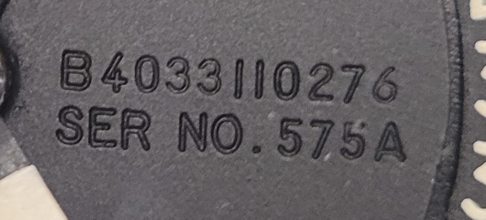
close-up of model and serial number on faceplate Face of instrument rear of instrument

Credit: My own photos

I believe my biggest and only leap was figuring out where the dashes went in the model number...

$\endgroup$
6
  • $\begingroup$ Side question: Is it safe to carefully disasseble the instrument without damaging it or injuring myself? I do not need to keep any kind of warranty or fit-for-use, and I doubt it could even qualify considering how I obtained it anyway. $\endgroup$
    – Steve
    Commented Jul 7, 2023 at 3:18
  • $\begingroup$ Stretch bonus: Can I trace where this came from? $\endgroup$
    – Steve
    Commented Jul 7, 2023 at 3:38
  • $\begingroup$ I did find this standard, but I think it would set general performance minimums that need to be net by altimeters in general, as opposed to how they actually must operate or interface (to some extent). sae.org/standards/content/as8009c/…. $\endgroup$
    – Steve
    Commented Jul 7, 2023 at 8:41
  • 2
    $\begingroup$ Well, you are certainly not going to injure yourself by disassembling the instrument, unless you are extremely inept at using tools and stab yourself with a screwdriver etc -- it's not a like a bomb waiting to blow-- as far as damaging it, someone else could probably speak to that better, but seems to me if you are careful it should all work out ok-- $\endgroup$ Commented Jul 8, 2023 at 0:49
  • $\begingroup$ That's enough for me to proceed with something, thanks @quietflyer. $\endgroup$
    – Steve
    Commented Jul 9, 2023 at 2:01

1 Answer 1

3
+200
$\begingroup$

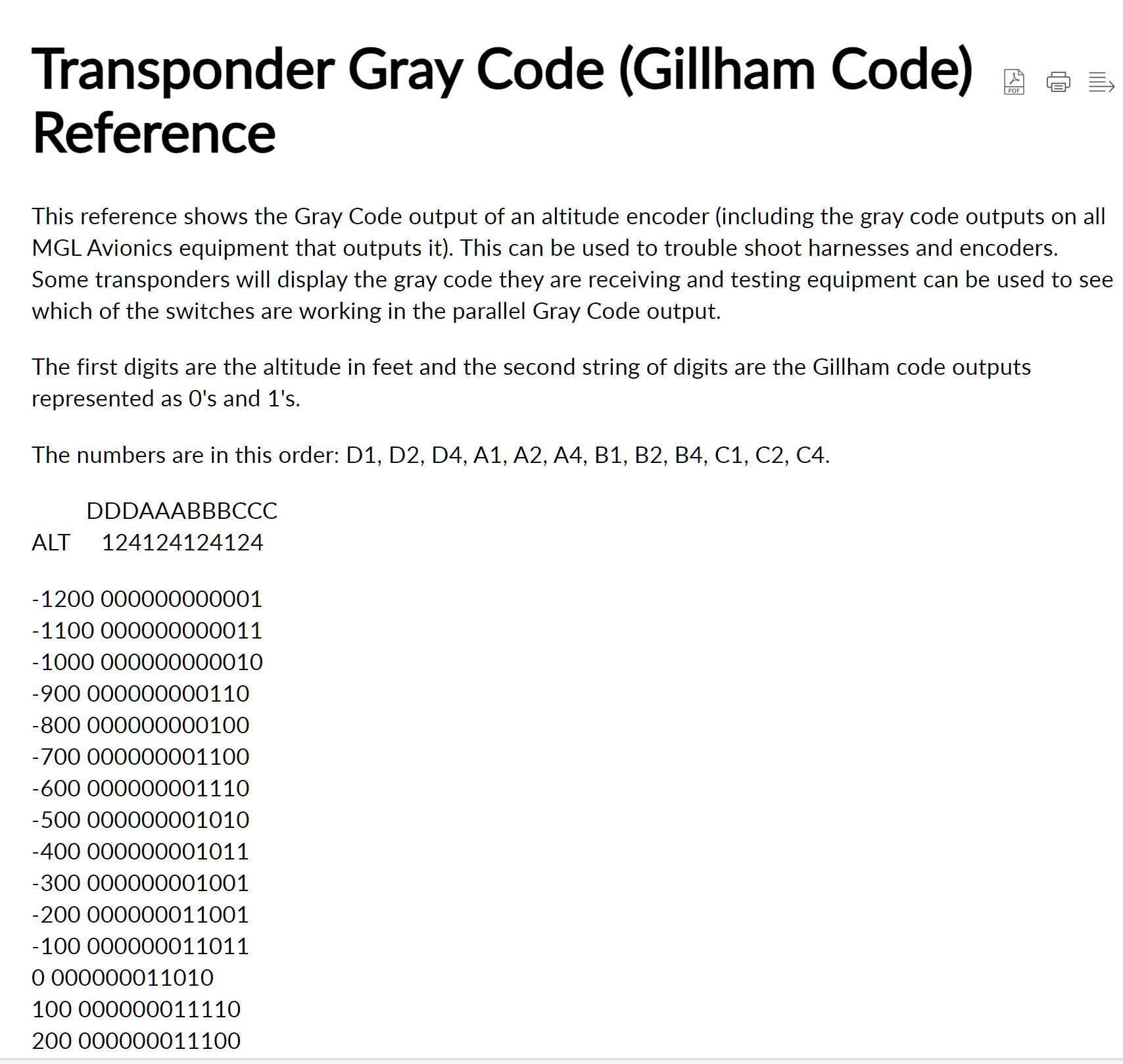
Undoubtedly an encoding altimeter. Ten pins are the encoder output. This is Gillham coded, a 12 bit Gray code identifying altitude in hundreds of feet. D4 is needed above 30750ft which makes ten pins. Power and ground are two more. Dimmer, serial data and/or strobe possible.

enter image description here

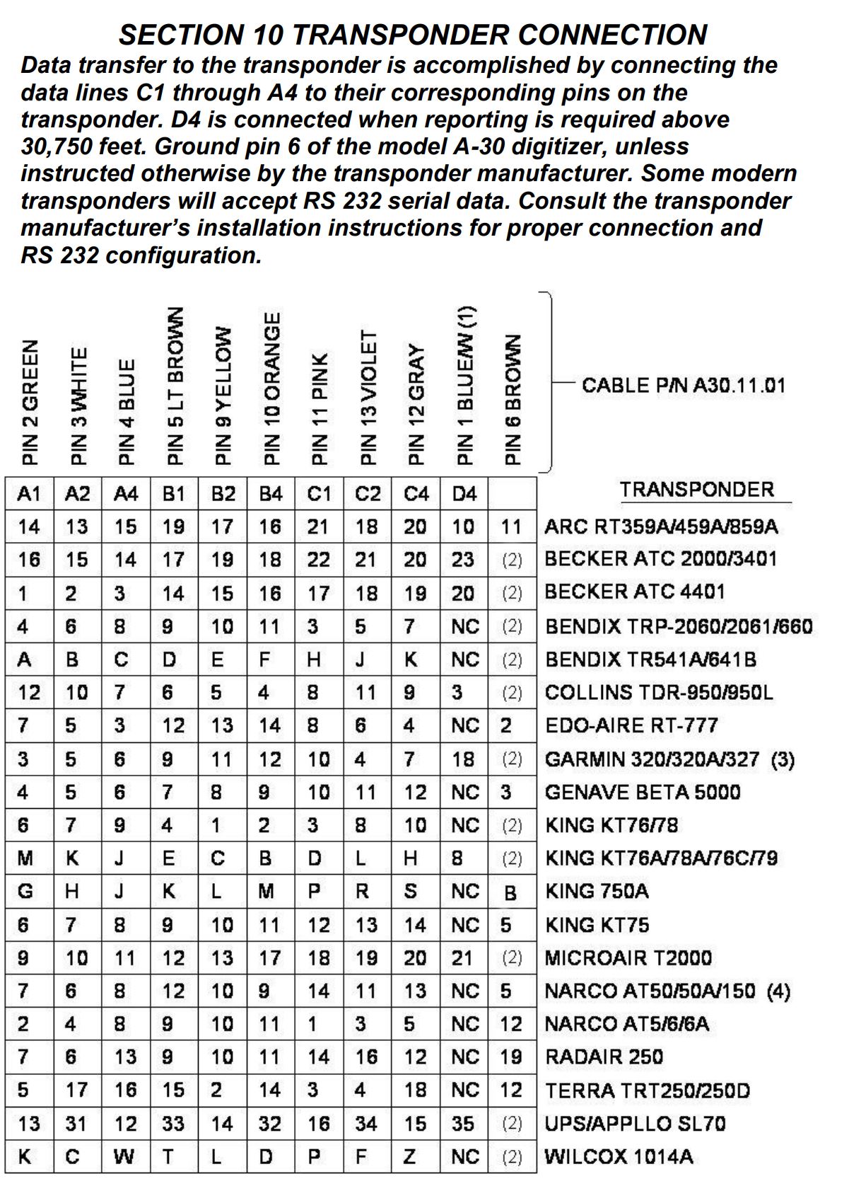
Sample transponder connections: enter image description here

Sample startup operation.

Electrical Connections: Use the 15 pin socket provided with the unit to make a wiring harness. The harness should have 14 wires: 10 for altitude data and one each for strobe, serial data, power, and ground... Most transponders have available switched power (A+) or a direct connection to the aircraft avionics bus may be made. When a connection to the avionics bus is made, a 2-Ampere circuit breaker should be installed. Connect pin 6 to ground if the transponder does not have a strobe connection... Pin 6 of the encoder connector is the strobe line. Logic low (less than 1.2 volts) on this pin enables encoder output.

When power is first applied to the encoder, all of the output data lines will pulse high/low. Each data line will then go high and low individually until all of the lines have been pulsed. This action is normal and serves as a diagnostic tool for the installer to use in verifying the encoder output and the harness on a line-by-line basis.

Yours may not do this. You can order a manual at Carp Ind. Search "B40331". No description as to service, operator or repair manual.

Kollsman is now a subsidiary of Elbit.

$\endgroup$
3
  • $\begingroup$ Any idea what the signaling is? Common emitter/pull to ground (e with pull up) or voltage levels, etc? $\endgroup$
    – Steve
    Commented Jul 14, 2023 at 5:50
  • $\begingroup$ @Steve Logic low is less than 1.2v. I don't have docs but logic high at 5v would be likely. $\endgroup$
    – Pilothead
    Commented Jul 14, 2023 at 11:56
  • $\begingroup$ I'm running out of time and can't get back to this project, so the bounty is yours! $\endgroup$
    – Steve
    Commented Jul 20, 2023 at 20:21

You must log in to answer this question.

Not the answer you're looking for? Browse other questions tagged .