2
$\begingroup$

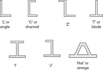
I am trying to add stringers on the skins of an aircraft's wing as well as fuselage, for the same reason why they are present in most of the aircrafts i.e. to resist bending (and a possible buckling scenerio when subjected to aircraft loads during flights) by adding stiffness to the structure. However, I am not sure what type of stringer should be used since there exists alot of variations, and some of them are shown in the picture below.

enter image description here

Since there exists so many variations, it makes me believe that some specific benefits are associated with each of these variations, when subjected to a certain situations. So what things should I consider while making the optimum choice for the stringer shapes? In which cases will each stringer shape prove to be fruitful than rest of the stringers? How should I decide the locations of these stringers within the top and bottom skins of the aircraft's wing and fuselage?

P.S: I can conduct a FEA for the wing + various shapes of these stringers, but it will take too much time. I believe there exists a rule of thumb for the choice of each stringer shape depending on somethings.

$\endgroup$

1 Answer 1

4
$\begingroup$

At the conceptual level, the most significant issue is whether the stringer has to be resistant to buckling; will it be subject to significant compression loads, or will be almost exclusively under tension? If compression loads aren't severe, the profile isn't that important and an L or T will work. If it has to take compression as well, you need the additional flange to stiffen the stringer against buckling without having to make the material thicker.

You will use the hat section when compression loads are really high. Next down would be the I and J profile, then the C or Z section, then the T or L. If the loads were pure tension, no stiffness at all is needed and a flat strip would do the job.

Access to fasteners and contact with adjacent objects also becomes an issue. You might use a Z instead of C because you want easy access to buck rivets. The C stringer will be harder to rivet. On the other, hand, the flange of the Z channel may foul on adjacent structure and force you to use the C channel.

$\endgroup$
8
  • $\begingroup$ So you are saying that addition of an extra flange (although this extra flange is not connected to any skin as the already existing flange on a T or L section is rivete/glued to the wing/fuselage skin) will still be a better choice for a moderately high compression load? I mean I can increase the thickness of the already connected flange instead of inputting an extra flange on the bottom of the stringer (like in C or Z). So which one will be a better choice? $\endgroup$ Commented Nov 7, 2021 at 19:44
  • $\begingroup$ For compression load through the skin along the axis of the stringer, where the stinger itself has to resist bending or buckling when compressed along its axis. For a given bending/buckling resistance, it'll be lighter to use a C or Z instead of making the vertical part of a T thicker, because the C/Z top flange adds the buckling resistance where it's most beneficial, along the top, whereas making it thicker, the extra material close to the base is not doing anything, just being ballast. Make a C section sample and and L or T sample from cardboard and see which is stiffer. It'll be obvious. $\endgroup$
    – John K
    Commented Nov 7, 2021 at 21:47
  • $\begingroup$ I don't know why you said that the other option is instead to increase the thickness of the web (vertical part) of T beam. I was thinking that I should be increasing the height of it (not the thickness) since for the same increase in mass, the increase in height will result in more stiffer T beam overall. $\endgroup$ Commented Nov 8, 2021 at 7:02
  • $\begingroup$ I was assuming you had to select a cross section limited to the same dimension. But making it higher adds nowhere near the resistance to buckling as bending the same extra material over into a flange, so I don't know why you would do that. $\endgroup$
    – John K
    Commented Nov 8, 2021 at 13:52
  • $\begingroup$ Well, I checked out how would the moment of inertia change for a T beam when extra height is added to its web, as compare to adding extra thickness to its web (where material addition in both cases is the same). It turned out that adding extra height to the web of T beam would result in more moment of inertia hence making the stringer more stiff and more effective against the top wing skin / fuselage buckling. $\endgroup$ Commented Nov 8, 2021 at 14:40

You must log in to answer this question.

Not the answer you're looking for? Browse other questions tagged .