All I know is that the valves open at low speed or when decelerating, and close at high speed or when accelerating. How do they prevent the compressor from stall or surge?
-
3$\begingroup$ Stall is prevented by anticipating pressure variation and maintaining pressure in a safe area using the VBV, as explained in the answer to Why does the CF6/CFM56 Turbofan Fan Frame contain 12 circular holes between the primary and secondary flow? The stall/surge process is explained in If the intake of a running jet engine is blocked for some short duration what would be the sequence of events following it? $\endgroup$– minsCommented Aug 6, 2021 at 10:29
-
$\begingroup$ @mins With all respect to the answers linked in the comment (which are good answers!), the answers do not explain why the stall occurs at low spool speeds (the latter linked answer explains a rotating stall induced by an incident, but not why gas turbines are designed to blow off air), I hope the answer below sheds some light on that. $\endgroup$– 0scarCommented Aug 31, 2021 at 13:45
1 Answer
Valves open at low speed to prevent the blades to stall. At low spool speed, or a low power setting (low power setting => less fuel added to the cycle => less power in the turbine and as such less power available for the compressor), the volumetric flow through the fixed geometry compressor passage becomes too large (with respect to the design value, the compression is less at lower speed), blow-off of some of the air reduces the volumetric flow downstream of the bleed ports.
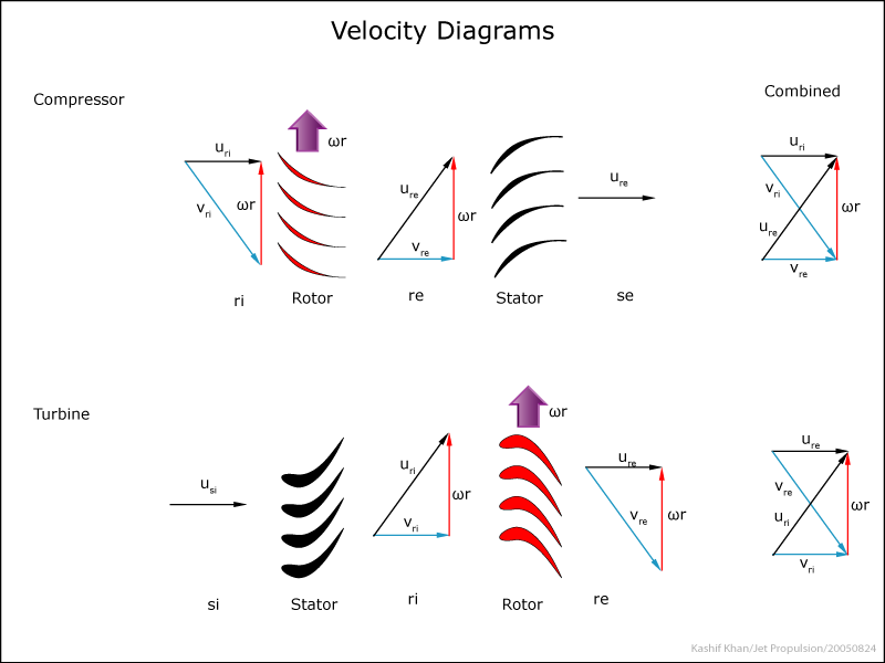
This can be explained with the so called velocity triangles/diagrams of the compressor:
The increase of the axial speed through the compressor (Uri increases) while the spool speed decreases (ωr decreases) causes the flow Vri angle (Uri - Vri) to become less steep and cause the flow to stall reducing the working of the compressor and blocking the flow passage; this is called surge. Blow-off of the air reduces the Uri flow velocity to prevent the compressor blades from stalling. Some compressors can change the geometry of the stator vanes to adjust for the change in inflow angle, this is referred to as Variable Stator Vanes, which extend the operating range. Bleed-off is the last resort to prevent surge.
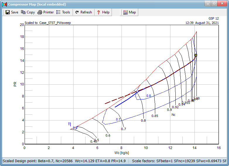
This can be easily visualized by simulation of a gas turbine. The following example shows a gas turbine steady-state performance sweep (reduction of fuel) of a typical helicopter turboshaft engine plotted in the compressor characteristic. The dashed simulation does not incorporate a bleed schedule and crosses the surge line on the left (since this is a simulation with extrapolated map characteristics, this is mathematically possible, but not in real life, the compressor would stall and airflow would stagnate), the solid blue line represents the performance where a surge margin of 10 % is maintained by bleeding off compressor air (hence the parallel operating line region at low power).
The image shows the steady state performance/equilibrium line in the compressor characteristic, the transient working line would show a way different profile. The reason that bleed-off may be interesting for spooling up (more fuel added for a higher power setting) is that an instant increase in fuel will cause the amount of reaction product to increase causing the pressure inside the gas turbine to rise at the same spool speed (due to the inertia, the spool spooling up is relatively slow) which results in the working point to go to the surge line (following the constant spool speed line). Usually the amount of fuel is limited by the controller which gradually adds the fuel. If the working point gets to close to the surge line, bleeding off compressor air will prevent the compressor to surge.
-
$\begingroup$ What software did you use to generate that plot? Is it open source, or otherwise available for use? Or if you didn't generate it, then what is the source of that image? I've often wanted something to plot compressor maps to answer questions like this one but never had any publicly available software to do it. $\endgroup$– Daniel KCommented Sep 1, 2021 at 0:17
-
$\begingroup$ @DanielK It's GSP, the Gas turbine Simulation Program, you can download a free copy at GSPteam.com. $\endgroup$– 0scarCommented Sep 1, 2021 at 5:06


