5
$\begingroup$

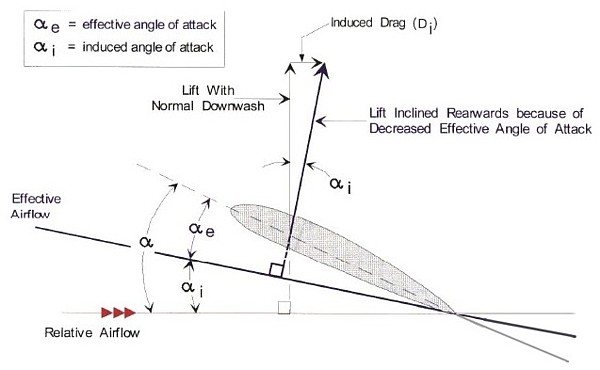
Does alpha induced angle/"effective airflow" really exist in real life on 3D wing or this is just mathematical concept for calculate induced drag?

(same as lifting line theory-circulation theory is just math concept for calcualte lift ,but everyone knows that airflow dont move around wing in circle...)

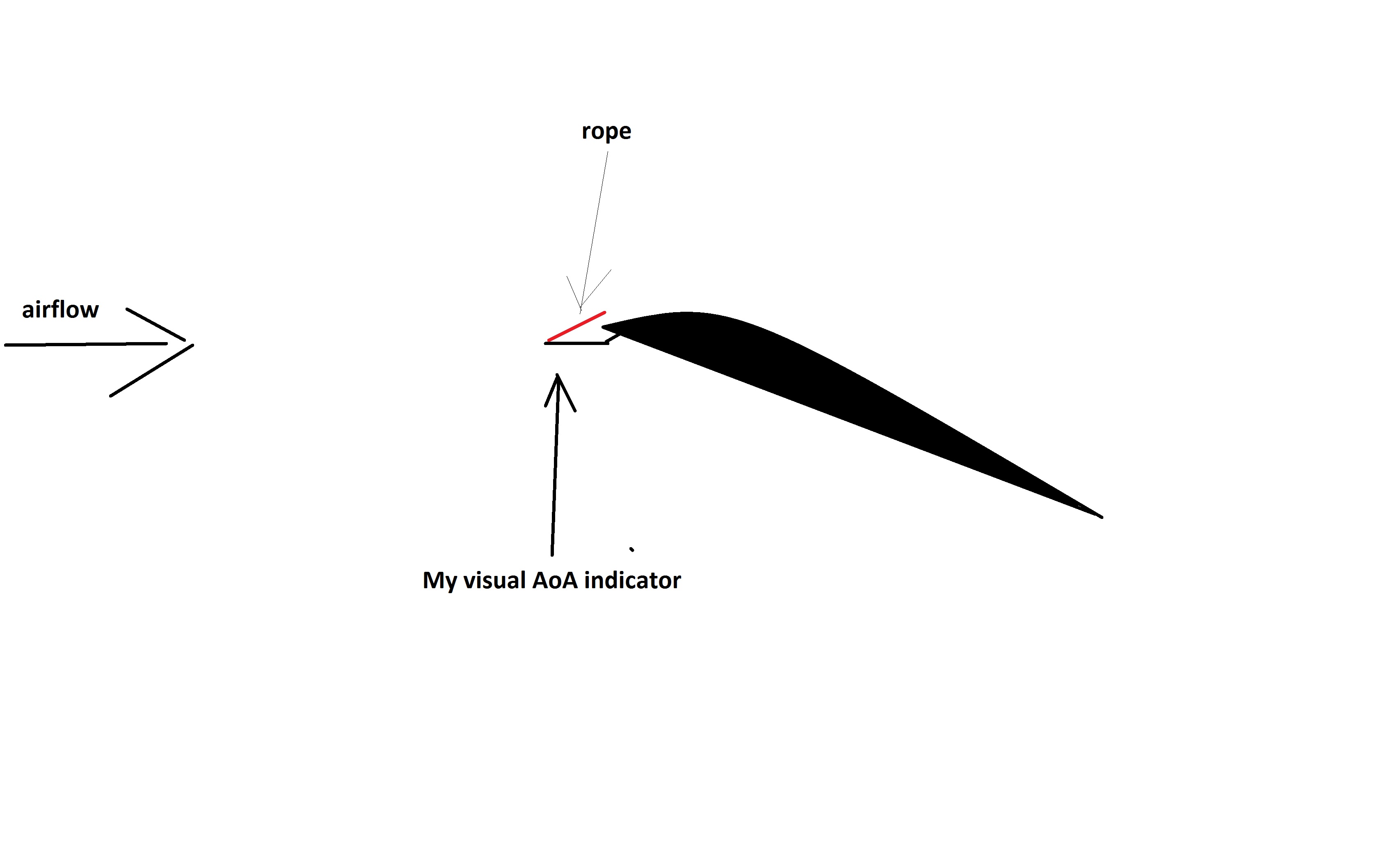
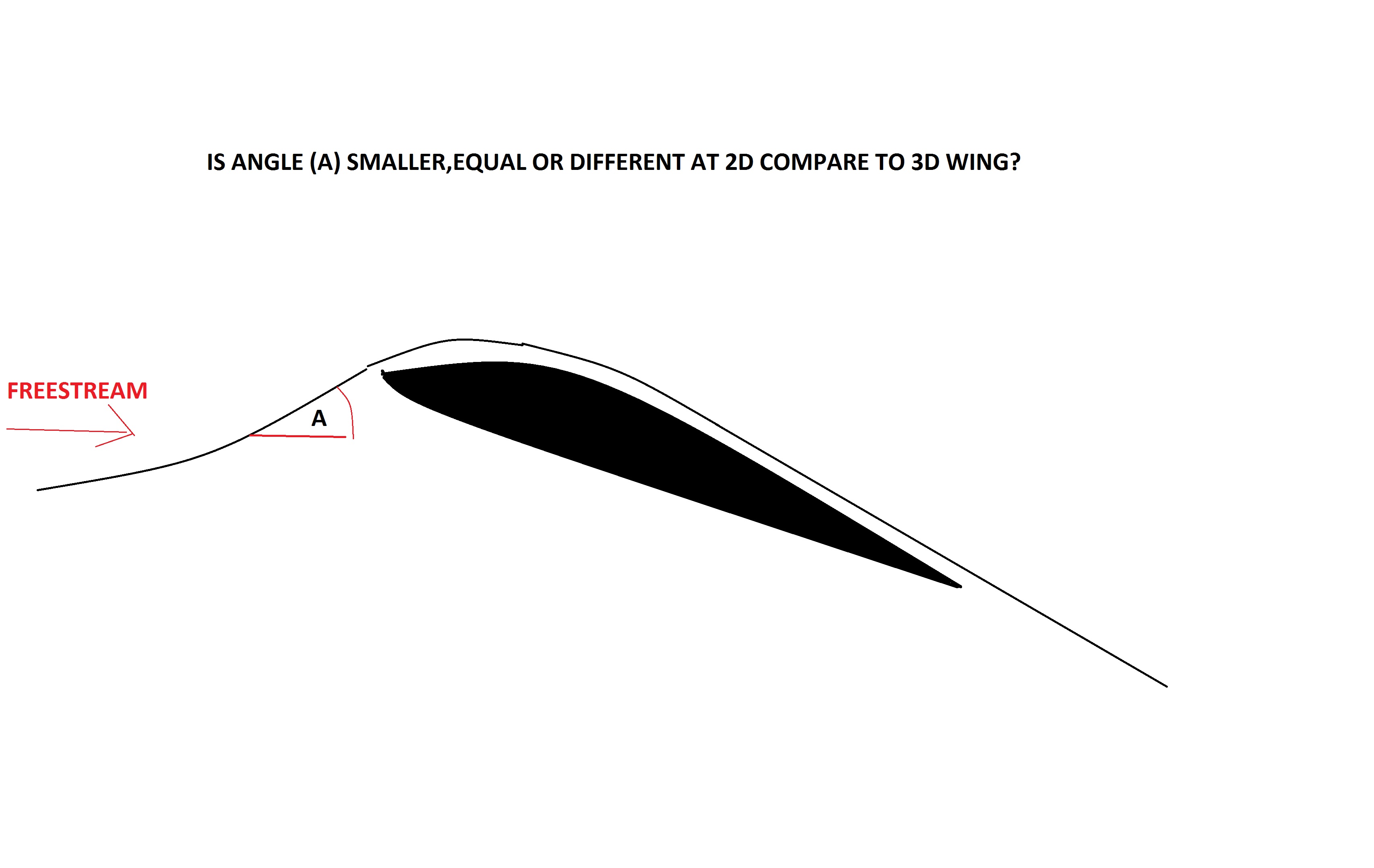
Question is ,if I put AoA-sensor infront of leading edge at same position at 2D and 3D wing,will be values different or equal?

(theory tell us that angle (A) at my picture below must be less on 3D wing than 2D wing...)enter image description here

(in my home made wind tunnel ,I cant see difference when I put visual AoA indicator infront of leading edge at 2D compare to 3D wing..so this is reason why I ask is this real thing(maybe angle is too small to see) or just math concept...all this mess with questions about induced drag on this forum ,starts when I do this experiments..)

enter image description here

enter image description here

here is exampels of visual AoA indicators:video 1 video 2

$\endgroup$
2
  • $\begingroup$ Congratulations for your AoA vane on the model airplane. Enjoyed watching the videos! $\endgroup$ Commented May 1, 2020 at 13:04
  • $\begingroup$ This is not my work I just put link of video..but yes nice to watch! $\endgroup$
    – ROTOR
    Commented May 2, 2020 at 20:18

2 Answers 2

5
$\begingroup$

1. Summary

Induced angle of attack is technically a mathematical concept. You can't measure it directly via flow sensors [from an isolated wing]. However, it is extremely useful in understanding and predicting the production of induced drag.

Just like Newton's theory of gravity is a mathematical abstraction; but, if it helps you in understanding and predicting outcomes, you might as well accept it as real. Read the following subsections if you want to understand the potential flow aerodynamic modeling a bit better.

EDIT: provided that you have an extremely long wing (and tunnel width) to call 2D section, and provided you have a corresponding high aspect ratio wing to call 3D section, the difference in AOA measured at the same chordwise location should converge to the induced AOA.

2. Lifting-Line

Induced angle of attack comes from an aerodynamic modeling method, called Lifting Line Theory, which approximates the whole wing as one single bound vortex line that changes in vorticity strength across the span. The change in vorticity is shed via trailing vortices across the span.

Since vorticity induces cross-flow, this model predicts net downwash (downward airflow) at every point along this vortex line. And since the wing is just a line, we can neatly separate out the free-stream velocity, which may have a free-stream angle of attack, or geometric angle of attack, against the line, and a downwash velocity that modifies the flow incidence, which we can call induced angle of attack.
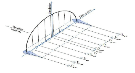
Lifting Line

Image ref: https://www.researchgate.net/figure/Lifting-Line-Theory-Scheme-Epps-2010_fig1_273450664

This simplified model predicts surprisingly accurate lift for straight, mid to high aspect ratio wing, in low subsonic flight. It also predicts a new kind of drag, called induced drag, which is totally absent in 2D subsonic [potential] flow.

Now, my question is, is any wing a single vortex line? Of course not. It's a model that gives very useful engineering results. The immediate shortcoming of the model is that it doesn't predict the flow field around the wing well, at all. How can it? It's a line!

3. Lifting-Surface

We can do better by approximating the whole wing as a lifting surface (or its cousin vortex-lattice), with the whole surface producing and shedding vorticity. This model is able to predict the flow field near the wing much better, by producing a different value of downwash at every spanwise and chordwise point. In front of the wing, there will be upwash. So if you measure flow incidence in front of the wing, you will measure higher incidence than the free-stream one.
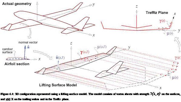
Lifting surface

Image ref: Drela, Flight Vehicle Aerodynamics

At this point, you should realize that the induced angle of attack is no more (because there is different downwash at every chordwise point). But for the same high aspect ratio, straight tapered wing, both lifting-line and lifting surface will agree on prediction of lift and induced drag.

So once again, is a wing a flat surface of vorticity? Of course not. Wing has thickness that lifting surface doesn't handle, and nor does it predict boundary layer.
$\endgroup$
14
  • $\begingroup$ This picture was stolen from the book "Flight Vehicle Aerodynamics" by the heli-air.net site admin. On top of that, Almost all the content on that website appears to be stolen contents from other sources. I would like to kindly request this REF to be removed from the heli-air.net and give rightful credit to the correct source which is mitpress.mit.edu/books/flight-vehicle-aerodynamics $\endgroup$
    – user46017
    Commented Apr 30, 2020 at 1:25
  • $\begingroup$ @m2as3registeredservicesohmone Thanks. But you do know that your comment here will not be heard by the guys at heli-air.net, right? $\endgroup$
    – JZYL
    Commented Apr 30, 2020 at 1:36
  • $\begingroup$ Thanks for the acknowledgement @JZYL. I don't mind me not being heard. Even I'm heard stealers are stealers and they gonna probability keep stealing others work anyway. On the personal level I have a great respect to the person who actually wrote that book and I have used the Latex package which was used to generate these figures. I know how hard it is to create these figures and how much thought the original Author might have put in to these. Thats the only reason for my request. $\endgroup$
    – user46017
    Commented Apr 30, 2020 at 1:51
  • $\begingroup$ @JZYL so induced alpha angle dont exist in reality and my AoA sensor will show equal angles for 2d and 3D wing.. Your answer is opposite from m2as3registeredservices ohmone..How do you comment his answer? $\endgroup$
    – ROTOR
    Commented Apr 30, 2020 at 7:51
  • $\begingroup$ @ROTOR Please read the bolded part in section 3 $\endgroup$
    – JZYL
    Commented Apr 30, 2020 at 11:06
2
$\begingroup$

Does alpha induced angle/"effective airflow" really exist in real life on 3D wing or this is just mathematical concept for calculate induced drag?

This induced angle really exist in real life on 3D wing. The physical reason why (what caused that induced angle) we see this induced angle is not the vorticity of the flow field though.

(same as lifting line theory-circulation theory is just math concept for calcualte lift ,but everyone knows that airflow dont move around wing in circle...)

I would not overgeneralize it as such myself. If you try to understand the derivation of lifting line theory I think you will be in a better position to appreciate it. Also, lift-circulation relationship comes from the Kutta-Joukowsky Theorem and not from the lifting line theory.

Also, the circulation is a generalized concept to indicate the strength of a point vortex. The general definition of the circulation is the integral of tangential velocity over any contour containing a point vortex. This DOES NOT mean airflow move around the wing in circles.

Question is ,if I put AoA-sensor in front of leading edge at same position at 2D and 3D wing,will be values different or equal?

Different values. In the 3D wing, the angle indicated should be lesser than that of the 2D wing.

(in my home made wind tunnel ,I cant see difference when I put visual AoA indicator in-front of leading edge at 2D compare to 3D wing..so this is reason why I ask is this real thing(maybe angle is too small to see) or just math concept...all this mess with questions about induced drag on this forum ,starts when I do this experiments..)

I for one would love to see some pictures of your home-made wind tunnel and experimental set-up.

PS1: This video from Doug McLean might be of help to understand it little better

PS2: As a completely general advise, Unfortunately, Its a little difficult subject to follow "Correctly", and as in any other scientific discipline, the problems and solutions tend to lie in different places than the majority of the people think where they are; so at least in a long run, probably it's a good idea to learn at least the basics enough to validate what's thrown your way. There are few very good free online courses on edx.org

$\endgroup$
3
  • $\begingroup$ @m2as3registerdservicesohmen,so you say that alpha induced angle exist in reality and we can prove it with AoA sensors...1)What is physical reason what cause alpha induced angle/shift in effective airflow 2)How do you comment JZYL answer,your answer is opposite from him $\endgroup$
    – ROTOR
    Commented Apr 30, 2020 at 7:56
  • $\begingroup$ I add picture concept and explantion $\endgroup$
    – ROTOR
    Commented May 1, 2020 at 16:40
  • $\begingroup$ With walls (2D test) I always get higher lift and DRAG than when I remove walls(3D test).So 3D wing(test without walls) I always get smaller lift and SMALLER DRAG then 2d test,for same AoA in both tests...Pressure loss on 3D wing outboard parts is so much,that lift and drag always drops.TESTO 510 always show significantly smaller pressure differential on wingtips at 3D wing,what is very logical because there is so much air LEAKAGE on it... $\endgroup$
    – ROTOR
    Commented May 4, 2020 at 7:23

You must log in to answer this question.

Not the answer you're looking for? Browse other questions tagged .