There's a really interesting paper by Manikandan Ramasamy (Hover Performance Measurements Toward Understanding
Aerodynamic Interference in Coaxial, Tandem, and Tilt Rotors, Journal of the American Helicopter Society, Vol. 60, 2015) that talks about this question, which is of great interest for multirotor UAS (which, for rotorcraft, is a substantial number of aircraft): how does stacking two rotor change their efficiency and thrust output?
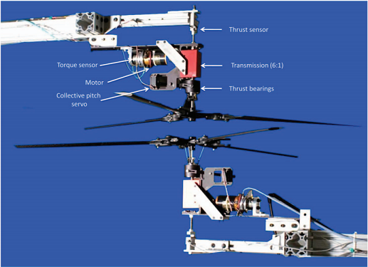
His test apparatus looked like this: two rotors located exactly one on top of the other, and his apparatus allowed him to measure both torque and thrust produced by each one independently. He could also vary the distance between the two rotors. For reference, the rotors are ~4.3 ft in diameter. Also, just to explain the graphs I'll throw up from his paper, he used blades both with and without twist.

The reason why he has torque sensors is going to come into play with the results. For a coaxial rotor helicopter (not necessarily for a coaxial prop airplane -- I am not sure which you care about), it is desirable to have a coaxial rotor setup wherein each rotor produces the same amount of torque. Multicopter UAS then disturb that torque balance to control themselves in yaw. For the tests Ramasamy performed, they were all done when the rotors were torque balanced, so each rotor produced a torque equal and opposite to the other rotor.
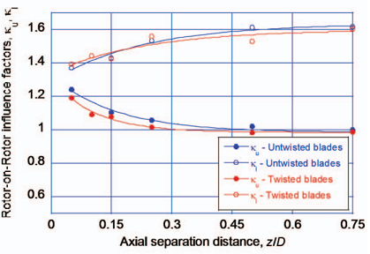
His results are pretty striking, as shown below. This is a plot of how "interference factor" for each rotor changed with respect to how close the rotors were to each other. "z/D" refers to the vertical separation of the rotors, z, as a fraction of the rotor diameter. The interference factor is a measure of the extra power required to turn the upper and lower rotors, ($\kappa_u$ and $\kappa_l$, respectively) as compared to an isolated rotor. An interference factor of 1 means the rotor is equivalent to an isolated rotor. Greater than 1 means that it is less efficient than an isolated rotor and vice versa.

As you see, as the rotors get further apart, the upper rotor acts as if it is all by itself ($\kappa_u=1$). However, the lower rotor is always more inefficient than an isolated rotor due to downwash from the upper rotor. That said, as the two rotors get closer, the effects get a little more wild.
As the lower rotor approaches the upper rotor, it helps pull air through the upper rotor, so you might think that the angle of the air hitting the blades is getting steeper (also called a higher inflow angle). This also leads to a lower angle of attack on the blades, leading to the following effects for the upper rotor: decreased thrust production (reliant on high angle of attack to produce more lift) and increases torque input (reliant on inflow angle). Consequently, $\kappa_u$ increases.
However, since the upper rotor is producing less thrust, the downwash on the lower rotor decreases...and, as you might imagine, it sees the opposite effect that the upper rotor sees: higher thrust production, lower torque input, and $\kappa_l$ actually decreases. Due to this, you now need to either slow down the upper rotor or speed up the lower rotor in order to achieve a torque balance.
Hence, the first answer to your question is...it depends, but it looks like you actually can get a more thrust out of the coaxial configuration (as opposed to two isolated rotors) if you can space the rotors out well. This is due, at least in part, to some "swirl recovery" performed by the lower, counter-rotating rotor. In other words, since a rotor not only pushes air down but also forces it to spin (like a tornado), the lower, counter-rotating rotor sees faster moving air and can take advantage of this to operate at a lower angle of attack: producing the same amount of thrust with lower drag penalties. However, the effectiveness of this, as said, varies with the separation of the two rotors.
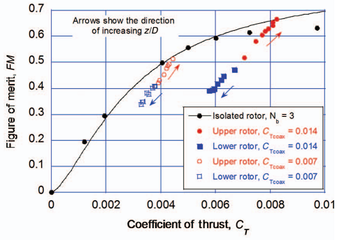
And, again, the larger issue, I think (from a performance perspective) in coaxial setups is not thrust production but power requirements. One of the two rotors (if not both) is always going to be less efficient than an isolated rotor producing the same thrust. This is shown more clearly below in a comparison of Figure of Merit (Fig. of merit = (Idealized power requirement)/(Actual power requirement), so a measure of rotor efficiency) versus coefficient of thrust (analogous to the amount of thrust produced by the rotor) for the rotors with untwisted blades.

In short, while you can get more thrust out of a pair of coaxial, counter-rotating rotors, there is no free lunch. And the lunch can get pretty expensive, at least from a performance point of view (not to mention the extra structure, etc. required for larger axial separation distances).


