In a steady-state climb in an airplane, the basic formula for the magnitude of the Lift vector is Lift = Weight * cosine (climb angle). For much more on this, see the vector diagrams and calculations in this related ASE answer. As long as the Thrust line is aligned with the flight path rather than being tilted up or down, the relationship Lift = cosine (Weight) is "baked into the physics" of a steady-state climb, even when we're flying at a high angle-of-attack that yields a high lift coefficient and a high L/D ratio. As long as Thrust is aligned with the flight path, Lift is less than Weight in a steady-state climb.
If any downthrust or upthrust is present relative to the direction of the flight path, then the situation becomes more complicated. Downthrust makes the Lift vector larger, and upthrust makes the Lift vector smaller. In the limit case where Drag is zero, Lift = Weight * cosine (climb angle) + Thrust * sine (downthrust angle), where the downthrust angle is defined relative to the direction of the flight path. (Treat upthrust as negative downthrust.) When Drag is not zero, then this formula no longer applies. When Drag is not zero, if there is downthrust, the Lift vector will be larger than the value given by the above formula, and if there is upthrust, the Lift vector will be smaller than the value given by the above formula. In such cases, the exact values of the Lift and Drag and Thrust vectors may be found by a vector diagram, if the L/D ratio and climb angle and downthrust or upthrust angle are known.
If enough downthrust is present, Lift will be greater than Weight in a steady-state climb. We can show that in the limit case where Drag is zero, whenever the downthrust angle relative to the direction of the flight path exceeds half the climb angle, Lift will exceed Weight. When Drag is not zero, the downthrust angle that makes Lift equal Weight becomes smaller than half the climb angle.
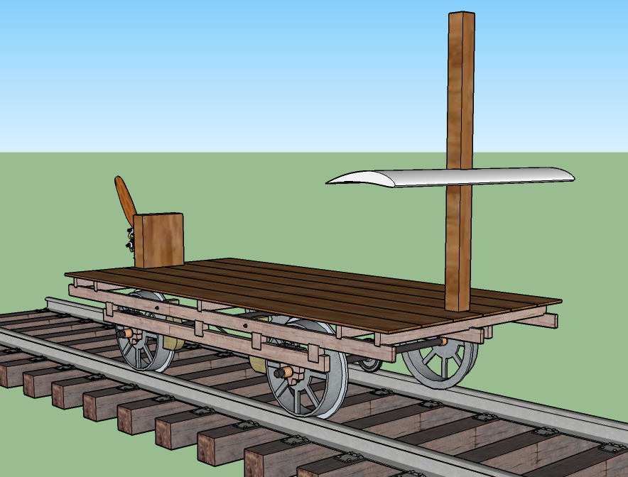
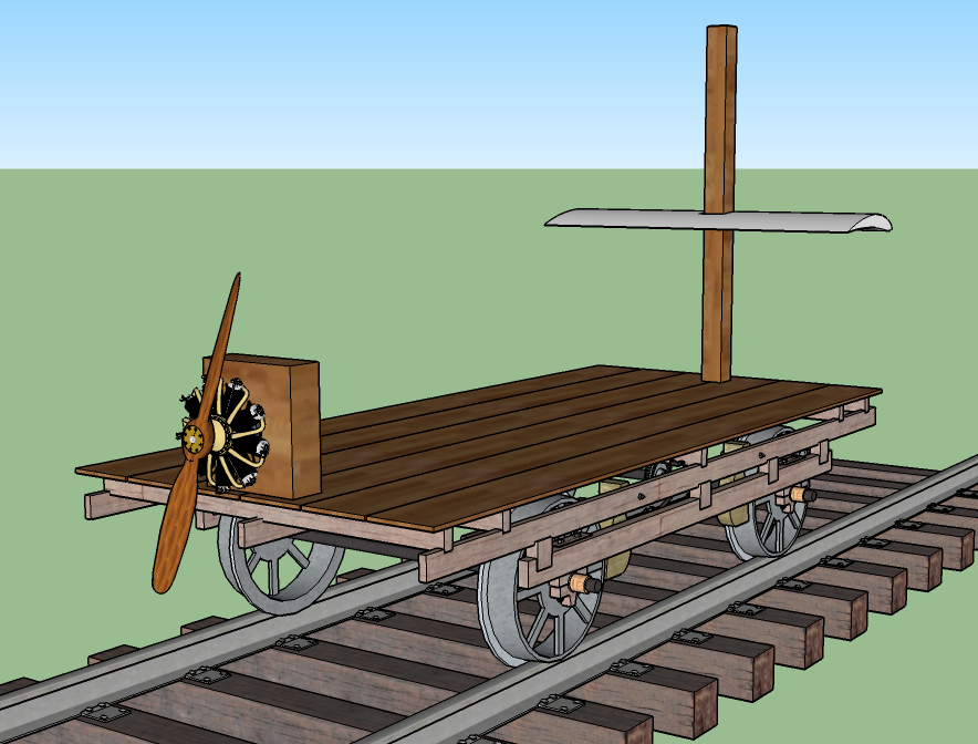
The cart of the "propeller train" can only push horizontally forward on the wing. So in the case of the "propeller train", as soon as the wing starts rising, the direction of the instantaneous flight path of the wing is no longer parallel to the thrust line, so downthrust exists. In fact, the downthrust angle is always exactly equal to the instantaneous climb angle of the wing. So whenever the wing of the "propeller train" is climbing, Lift must be greater than Weight, even in the steady-state case where acceleration is zero.
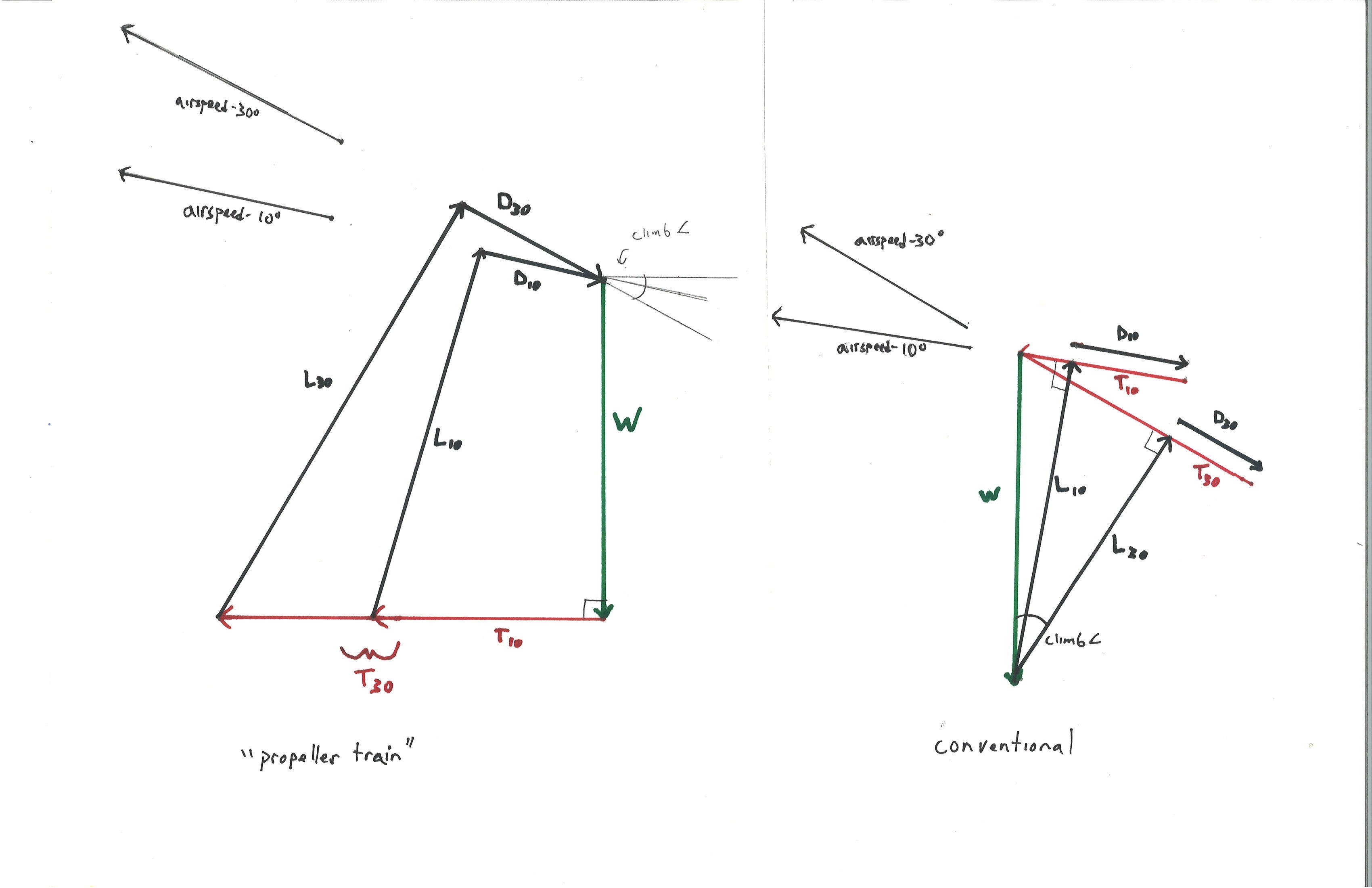
The vector diagrams immediately above show the forces in a steady-state climb for the wing of the "propeller train" on the left, and for a conventional airplane (where the downthrust angle at the given angle-of-attack happens to be zero) on the right.
For simplicity, the Lift to Drag ratio is 3:1 in all cases. 10-degree and 30-degree climb angles relative to the horizon are illustrated for both the "propeller train" and the conventional airplane. The diagrams are drawn to the same scale-- the Weight vector is identical in each diagram. The magnitudes of the airspeed vectors are scaled in proportion to the square root of the magnitude of the Lift and Drag vectors.
The right-hand diagram may look a bit odd with the "unattached" Drag vectors, but look closely and you'll see two closed right triangles, each comprised of Weight, Lift, and (Thrust minus Drag), with Lift = Weight * cosine (climb angle) and (Thrust minus Drag) = Weight * sine (climb angle).
(As an aside, the right-hand diagram may be easily modified for any L/D ratio by erasing or extending the right-hand ends of the Drag and Thrust vectors, keeping the value (Thrust-Drag) the same. It's not so simple to modify the left-hand diagram for different L/D ratios--the diagram must be completely re-drawn.)
Here is a table of the forces involved, with L/D fixed at 3:1, Weight arbitrarily set at 100, and airspeed ("A") in arbitrary units. We also have included the Power required (P). Since Power = force * the velocity component along the direction that the force is acting, Power is computed by multiplying Thrust times Airspeed times the cosine of the downthrust angle.
(3/1 L/D)
             "Propeller Train"              "Conventional" Airplane
Climb angle  L    D    T    A    P          L     D   D-T   T    A    P
      0      100  33   33   100  3300       100  33   0     33   100  3300
     10      115  38   69   107  7260       98   33   17    50   98   4920
     30      145  48   114  120  11900      87   29   50    79   93   7300
It's clear that more Power must be applied to the wing of the "propeller train" when the wing is rising upward than when it is not, just as with the "conventional airplane".
Just for comparison, here are the forces and power requirements resulting from an L/D of 10/1 rather than 3/1-- (the vector diagrams corresponding to these cases are not reproduced here)--
(10/1 L/D)
             "Propeller Train"             "Conventional" Airplane
Climb angle  L    D    T    A    P          L     D   D-T   T    A    P
      0      100  10   10   100  1000       100  10   0     10   100  1000
     10      104  10   29   102  2890       98   9.8  17    27   99   2700
     30      125  12   75   112  7280       87   8.7  50    59   93   5460
Warning-- we shouldn't assume that the 3/1 L/D table and the 10/1 L/D table could both reflect the same aircraft or wing, at two different angles-of-attack. If we want to use the tables in that way, we must ignore the "Airspeed" and "Power" columns. The reason for this is that the Airspeed and Power columns are arbitrarily set for each table so that a Lift vector of 100 correlates to an Airspeed of 100. In reality, when we put the stick or yoke forward and decrease the wing's angle-of-attack and L/D ratio, we also decrease the lift coefficient, causing a large increase in airspeed that it is not reflected in the tables. The "Airspeed" and "Power" numbers on the tables are only meant for comparison between different climb angles at the same L/D ratio, or for comparison of the "propeller train" and "conventional airplane" cases at the same L/D ratio and climb angle, assuming that the lift coefficient is the same in each case.
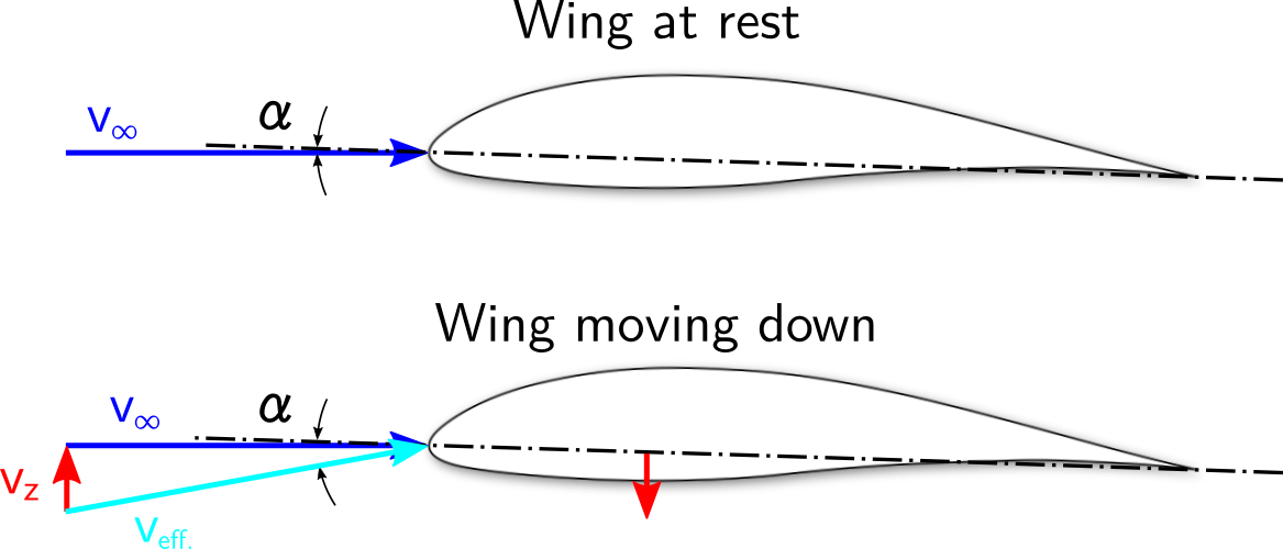
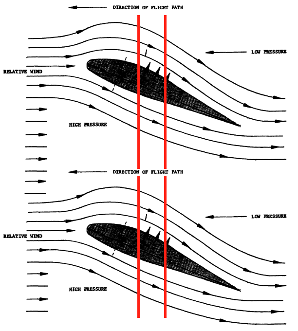
Note that in reality, unless the wing of the "propeller train" is free to pivot in pitch, the angle-of-attack of the wing of the "propeller train" cannot actually stay constant regardless of climb rate-- the higher the climb angle, the more the "relative wind" comes down from above, relative to the horizon. This decreases the airfoil's angle-of-attack. Therefore the L/D ratio cannot actually stay constant as the climb angle increases. Unless the wing is fixed at a very nose-high pitch attitude so that it is essentially stalled when it is not rising, higher climb angles will be correlated with lower lift coefficients, and therefore with higher airspeeds. And as long as we are on the "front side" of the Drag curve, the lower angles-of-attack caused by higher climb angles will be correlated with lower L/D ratios. With the "propeller train", in the steady-state condition, a decrease in L/D ratio is reflected not as a decrease in Lift, but rather as an increase in Drag, Thrust, and Lift. This is best visualized by looking at the left-hand vector diagram and seeing what else changes when we increase the length of the Drag vector, while holding the climb angle constant.
In essence, the vector diagrams and tables above give some insights into how the downthrust angle affects the forces acting on the wing of the "propeller train", and they also clearly show that the wing of the "propeller train" demands more Thrust and Power when it is rising than when it is not, but they pertain most directly to a wing free to pivot to maintain a constant angle-of-attack and L/D ratio regardless of the fuselage pitch attitude, along the lines of the "freewing" concept (link to PDF) (better link needed).
Another interesting variation of the "propeller train" concept would be , or a spinning cylindrical wing using the "Magnus" effect (Wikipedia link) in which case the magnitude of the Lift and Drag vectors would be insensitive to the direction of the relative wind.
What insights does the "propeller train" give us about flight in a conventional airplane? It tells us that it is possible to enter a climb without pitching up at all, so that the aircraft's pitch attitude stays the same as it was in horizontal flight, but in most cases it is extremely inefficient. If we are initially flying very slowly, on the "back side of the Drag curve", at a very high angle-of-attack and a nose-high pitch attitude, adding power while holding the pitch attitude constant will indeed cause us to gain airspeed and start climbing. In this part of the flight envelope, this strategy works just fine.
However if we are in anything like normal cruising flight, we'll find that adding power while holding the pitch attitude constant can only produce a very modest climb rate and climb angle. As we enter the climb, to prevent the aircraft from pitching up to maintain the same angle-of-attack it had in horizontal flight, we'll be holding forward pressure on the control stick or yoke to decrease the angle-of-attack, or we'll re-trim the aircraft to accomplish the same thing. Unless we're on the "back side" of the Drag curve, the decrease in angle-of-attack associated with climbing will degrade the L/D ratio, and unless our aircraft had substantial upthrust relative to the flight path when it was flying horizontally, any positive climb angle will introduce downthrust relative to the direction of the flight path. If we're starting from normal cruising flight on the "front side" of the Drag curve, all these relationships work against us, and we'll find that it takes a very large increase in airspeed, Thrust, and Power to achieve a very modest climb rate and climb angle.
The "propeller train" thought experiment makes it clear why we normally enter a climb by allowing the aircraft to pitch up so that the angle-of-attack is not decreased by virtue of the aircraft's rising trajectory, and the thrust line is not pointed downward relative to the flight path, regardless of whether or not we actually choose to increase the angle-of-attack as we enter the climb.
No power invested by the propeller goes into potential energy of the
wing; the climb of the wing is done purely by lift. Did I miss
something?
Yes-- with the "propeller train", when the wing is rising, thrust certainly is doing work along the direction of the flight path through the airmass, which is never purely vertical. Here's an analogous situation-- imagine a kite flying on a windy day, with the string at a 45-degree angle. Imagine that we have a lightweight ball that can dangle from a hook that we can clip over the kite string. The purely horizontal force from the wind will make the ball run up the kite string. The wind is doing work that increases the potential energy of the ball, and the propeller of the "propeller train" is doing work that increases the potential energy of the wing.
Related links:
Does lift equal weight in a climb? -- includes vector diagrams
Are there any situations where having high lift but low lift to drag ratio would be beneficial? -- includes a focus on lift and drag coefficients as well as the actual force vectors, in climbing flight
Is excess lift or excess power needed for a climb? -- examines the present question in exhaustive detail, not limited to the steady-state condition of constant climb rate, and includes a modified version of problem where the wing of the "propeller train" is free to pivot to maintain constant angle-of-attack
