After reviewing discussions and vector diagrams of gliders in flight, the vertical lift component and the vertical drag components seem to produce a steady state, 0 acceleration balance with gravity. The glider is on a straight line flight towards the ground. Would the forward motion of the glider be accounted for by combining the horizontal lift vector and gravity? Would any other forces be involved?
-
2$\begingroup$ See also: How can an airplane keep going forward if it has no thrust? $\endgroup$– ZazCommented Nov 13, 2018 at 14:17
-
$\begingroup$ Comments are not for extended discussion; this conversation has been moved to chat. $\endgroup$– foootCommented Mar 23, 2020 at 1:44
6 Answers
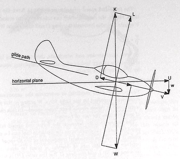
V is the airspeed. U and w are the horizontal and vertical components of V. The rest of the vectors are forces; W = weight, K = aerodynamic force, L & D are the orthogonal components of K. Those are all the forces involved in a glide.
-
$\begingroup$ I was hoping someone would say V is a combination of velocity down and velocity forward (created by horizontal component of lift vector). Interesting that, even though acceleration forces are in balance. Can we have a "relative velocity" direction based on falling and moving forward at a constant speed? $\endgroup$ Commented Oct 23, 2018 at 20:37
-
$\begingroup$ Better yet, what generates "U"? $\endgroup$ Commented Oct 23, 2018 at 20:49
-
$\begingroup$ The projection of the weight vector is the 'thrust' that opposes the projection of the aerodynamic force (drag). As those forces are in equilibrium, the motion is uniform, with a constant speed and zero acceleration. $\endgroup$– xxavierCommented Oct 23, 2018 at 21:13
-
$\begingroup$ Airspeed is not a force. V would be the trust component. The question is what is providing the thrust component that is opposing drag. $\endgroup$– TomMcWCommented Oct 23, 2018 at 22:26
-
$\begingroup$ Force U is 90 degrees to gravity there for can not be created by it. The horizontal component of lift is not drawn (why?). Gravity cannot be moving the plane forward any more than gasoline can provide thrust. Is not the wing the "engine" of lift and thrust, as in birds? $\endgroup$ Commented Oct 23, 2018 at 23:12
"What produces Thrust along the line of flight in a glider?" Nothing. There is no Thrust involved in gliding flight. Lift, Drag, and Weight form a closed vector triangle, meaning net force is zero, meaning no acceleration or deceleration is taking place. The Weight vector can be resolved into components perpendicular and parallel to the Drag vector, but noting that Weight has a component that is parallel to Drag is not the same as saying that a Thrust force exists.
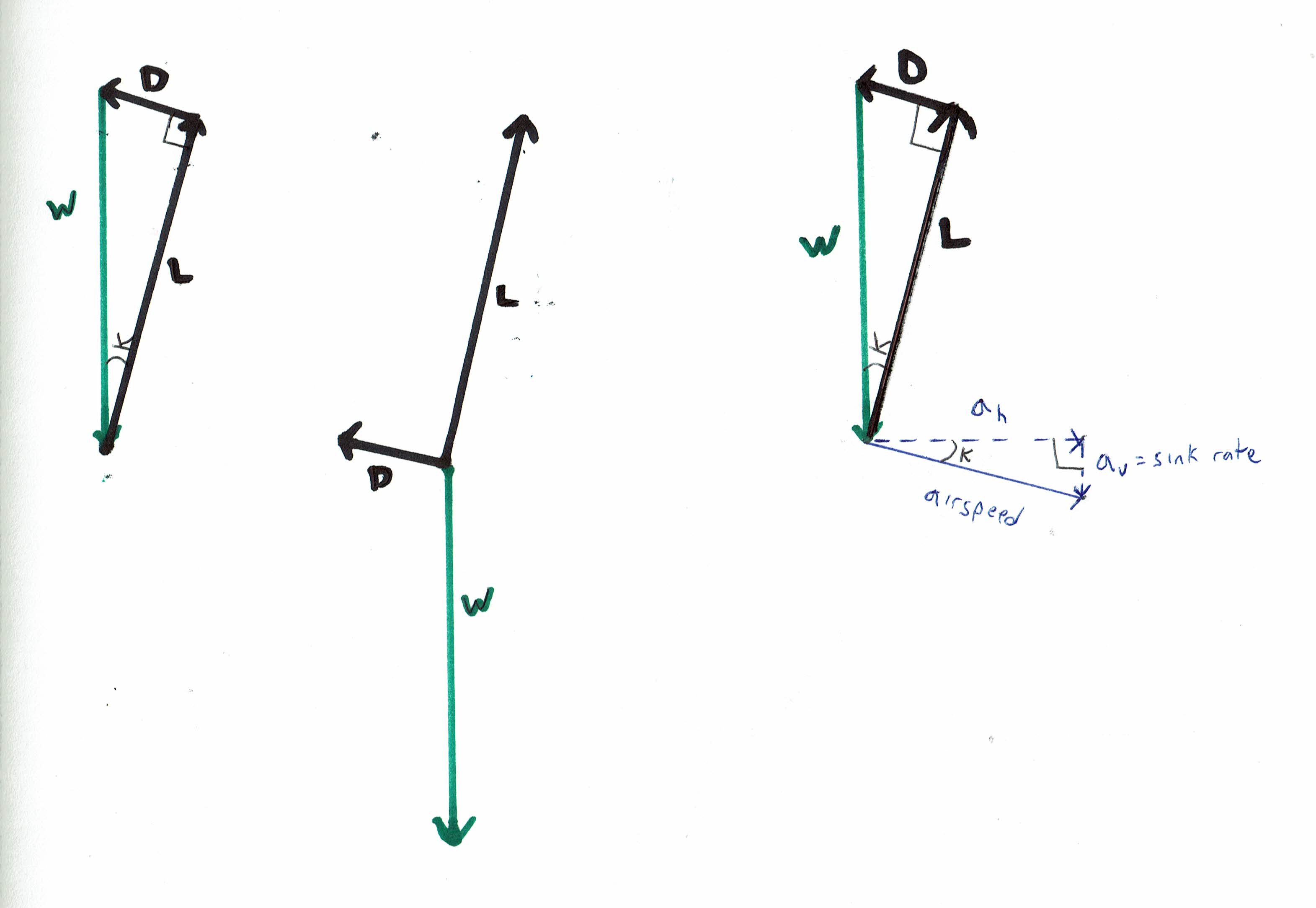
See these vector diagrams:
The balance of forces in gliding flight can be represented by a closed vector triangle of Lift, Drag, and Weight, with right angle between the Lift and Drag vectors. If we wish, we can also show the airspeed vector, and we can break it down into its horizontal and vertical components. The vertical component of the airspeed vector is simply the sink rate.
All three of the above vector diagrams represent the exact same physical situation. We've represented the aerodynamic forces in black, and the gravitational force-- the weight vector-- in green. The left-hand and right-hand diagrams are easier to understand than the middle diagram, because the force vectors are arranged into a closed polygon (a triangle in this case), which shows us instantly that the net force is zero. On the right-hand diagram, we've also included the airspeed vector, and its horizontal and vertical components. Note that K is the glide angle, and note that on the right-hand diagram, the triangle formed by the force vectors and the triangle formed by the airspeed vectors are similar triangles. The right-hand diagram makes it immediately obvious why the ratio of Lift to Drag, is also equal to the glide ratio through still air-- i.e.the ratio of horizontal speed to vertical speed (sink rate). Note that for high L/D ratios, Lift is very nearly as large as Weight, and horizontal speed is very nearly as large as airspeed, so for most practical purposes we can use airspeed / sink rate, glide ratio, and L/D interchangeably.
Note that if we wish, we can break the Weight vector down into two components, one of which is exactly equal in size and opposite in direction to the Lift vector, and one of which is exactly equal in size and opposite in direction to the Drag vector. The latter can be viewed as being somewhat like Thrust, but it's not strictly correct to label it as such.
The lift vector is proportional to the lift coefficient times the airspeed squared. The drag vector is proportional to the drag coefficient times the airspeed squared. The ratio between the magnitude of the Lift and Drag vectors is identical to the ratio between the lift and drag coefficients. For a given fixed aircraft shape, a change in the lift coefficient and/ or drag coefficient represents a change in angle-of-attack. Every possible angle-of-attack of the wing is associated with a specific lift coefficient, a specific drag coefficient, and a specific Lift : Drag ratio. This is true regardless of whether the aircraft is heavy or light-- a change in weight is expressed as a change in the airspeed associated with any given angle-of-attack, but no change in the lift coefficient, drag coefficient, or Lift: Drag ratio associated with any given angle-of-attack.
It is crucial to understand that the above vector diagrams will be valid for flight at some given particular angle-of-attack of the wing REGARDLESS of whether the airmass is rising, sinking, or neither. A glider doesn't feel any difference in the direction and magnitude of the forces acting on it when rising in a powerful mountain wave, than when gliding in still air.
Note also that we're only dealing with the wings-level case. In circling flight, the forces still look the same in a side view, but airspeed and lift and drag are all higher than in wings-level flight at the same angle-of-attack, and the glide ratio is decreased, and from a head-on view we'd see that the part of the lift vector has been diverted to the side.
Back to the simple case of wings-level flight--
What is "powering" the glider?
Work is proportional to force times distance, and power is proportional to force times velocity. In the airmass reference frame, the glider's direction of travel is identical to the direction the airspeed vector is pointing. The only force doing work on the aircraft in this direction is the component of the weight vector that points in the same direction as the airspeed vector. We can break the Weight vector down into one component that is equal and opposite to the Lift vector, and one component that is equal and opposite to the Drag vector. The latter component is what is "powering" the glider, at least as viewed from the standpoint of the airmass reference frame. The latter component of the Weight vector will be equal to Weight * cosine (glide angle). So the Power exerted by this component of the Weight vector is equal to (Weight * cosine (glide angle)) * airspeed). Now, it just so happens that the sink rate is equal to (airspeed * cosine (glide angle)). So we can say that the power exerted by gravity = (Weight * cosine (glide angle)) * airspeed) = (Weight * (cosine (glide angle)) * airspeed) = Weight * sink rate.
As viewed from the ground reference frame, the glider's direction of travel is different when the glider is in rising airmass than when the glider is in still air, so the above formulae for work and energy will only be valid in still air. From the ground reference frame, the glider's direction of travel is sometimes horizontal or climbing, in which cases the Lift vector can be viewed as having a component that is doing work on the glider. But as noted earlier, the direction and magnitude of the Lift, Drag, and Weight vectors remains the same regardless of what reference frame we are using for our velocity vectors.
(Note-- this answer is focused on linear steady-state gliding flight. It is not intended to address a case where the glider is accelerating. Note that a change in airspeed will affect the magnitude of all the aerodynamic force vectors, and note that any imbalance between L and the opposing component of the W vector will make the flight path curve up or down. The topic of how, starting with some imbalance between L D and W, a glider transitions back to a steady-state case where L, D, and W are again in balance (in the absence of corrective control inputs from the pilot, typically via a series of gradually decreasing "phugoid" oscillations involving continual variations in glide or climb angle, vertical speed, airspeed, pitch attitude, and to some extent angle-of-attack), is a fascinating one but beyond the intended scope of this answer. Likewise the subject of loops and other aerobatic maneuvers, or any other form of accelerated flight.)
See related answers to related questions:
An airplane has an engine that pushes its flight. What force pushes a glider to fly?
"'Gravitational' power vs. engine power" -- https://aviation.stackexchange.com/a/56040/34686
"Descending on a given glide slope (e.g. ILS) at a given airspeed— is the size of the lift vector different in headwind versus tailwind?" -- https://aviation.stackexchange.com/a/56259/34686
"Does lift equal weight in a climb?" -- https://aviation.stackexchange.com/a/56476/34686
-
$\begingroup$ @RobertDiGiovanni
weight can only go straight down and cannot be resolved into vectors.But you asked what propels it along it's flight path. Gravity can be divided into vectors wrt an angled flight path. BTW, if you got what you came for you should accept one of the answers. $\endgroup$– TomMcWCommented Oct 24, 2018 at 17:26 -
$\begingroup$ "weight can only go straight down and cannot be resolved into vectors. "- sure it can. The force vector called Weight (= mass * grav. constant) can be resolved into an infinite number of pairs of two other vectors, each with a 90-degree angle between them. For the purposes of this diagram someone decided to resolve Weight into two vectors acting parallel and perp. to the flight path. Personally I think it makes a better diagram if you just draw a closed vector triangle involving Weight, Lift, and Drag and be done with it; forget about resolving the forces into pairs of orthogonal components. $\endgroup$ Commented Oct 24, 2018 at 22:24
-
$\begingroup$ This answer would be improved by noting somewhere near the beginning, that lift is less than weight (lift = weight * cosine glide angle), as shown by the diagrams. $\endgroup$ Commented Nov 2, 2018 at 21:01
-
$\begingroup$ @quietflyer You have a problem conceptually. DWL forms a triangle, but it can only be said that they are balanced. That is, "thrust" is balanced with D. So it was the glider moving at a constant speed. Of course, DWL can also be unbalanced. When the "thrust" is greater than D, the speed of the glider will increase. $\endgroup$– enbinCommented Mar 22, 2020 at 10:40
-
$\begingroup$ @enbinzheng -- DWL either form a closed vector triangle, or they don't. I'm addressing steady-state constant speed linear flight, where they do form a closed vector triangle. So your comment is really off-topic from my answer. Talking about the dynamics of how the glider comes back balance starting from a given situation where there is not a closed vector triangle is an interesting and complex topic, but off-topic from my answer. $\endgroup$ Commented Mar 22, 2020 at 12:44
In a steady state with no acceleration nothing needs to produce a forward force. Inertia indicates that all forces are equal. This is true whether climbing, descending or maintaining constant altitude.
That given, there will always be a drag force trying to slow the glider along its flight path. To remain at a steady airspeed it is only this drag force that must be overcome. Since a glider produces no thrust, drag must be compensated by angling the flight path downward causing a portion of gravity to counter the drag force. If you divide gravity into x and y coordinates referenced to the flight path it is the portion that is parallel to the flight path that is countering the drag.
This is all presuming no updraft.
-
$\begingroup$ Even in an updraft the forces are exactly the same, and the velocity vector drawn RELATIVE TO THE AIRMASS REFERENCE FRAME is exactly the same. If you happen to be standing in a rising elevator as you look at the diagram, you'll know what I mean. $\endgroup$ Commented Oct 24, 2018 at 22:19
-
$\begingroup$ @quietflyer Yeah, but an updraft complicates things. The flight path is no longer the same angle wrt gravity and it provides an additional aerodynamic force. I was just keeping it simple $\endgroup$– TomMcWCommented Oct 24, 2018 at 22:30
-
$\begingroup$ Actually the flight path with respect to the airmass is at the same angle to the horizon in updraft, downdraft, and still air, and the aerodynamic forces are identical in all three situations. $\endgroup$ Commented Oct 24, 2018 at 23:54
-
$\begingroup$ @quietflyer engineering.stackexchange.com/q/26575/19873This is a human-powered aircraft I have considered. Do you think it is possible? Welcome to discuss. $\endgroup$– enbinCommented Mar 22, 2020 at 21:32
It might be easier for you to understand this from an energy balance standpoint, as follows: The vertical descent rate in feet per second of a glider times its weight yields the energy release rate (foot-pounds per second) being dissipated by drag forces as it descends. Dividing the energy release rate by 550 yields the horsepower required to maintain the glider in its glide. This energy is being dissipated by a drag force applied to the airframe; that force times the airspeed yields the drag horsepower. In a steady-state glide, the descent horsepower equals the drag horsepower.
-
$\begingroup$ Ok, for (academic) fun, we have gotten from fuel (gravity) to energy release (engine), what is the propeller ? What gets the glider moving forward? Very basic, but important, as this is the "incipient glide" Once the aerodynamic (from falling) forces push the nose down and airflow starts over the wing (propeller). Gravity does not do this. Airflow does. Diagram could be better. $\endgroup$ Commented Oct 24, 2018 at 10:58
-
$\begingroup$ But I do like the concept of steady state drag horsepower, as it could be used to determine thrust requirement for powered flight. I had imagined Weight x Inverse of glide ratio. Applied it to can a 747 fly on one engine and it was close! $\endgroup$ Commented Oct 24, 2018 at 11:01
-
$\begingroup$ Robert don't you remember that this was recently explored in detail here? aviation.stackexchange.com/questions/56023/… and aviation.stackexchange.com/a/56040/34686 . But weight * sink rate -- the approximation discussed in the answer-- is not the same as weight * inverse of glide ratio. $\endgroup$ Commented Oct 24, 2018 at 22:29
-
$\begingroup$ I was pointing out that weight x inverse glide ratio gave a fairly close answer for minimum power maintain altitude, and indeed, involves sink rate. But thanks, I will review these articles. $\endgroup$ Commented Oct 25, 2018 at 1:42
What creates force U? We know the glider is descending vertically at a constant velocity. We know the wing is pitched down at an angle. How does this translate into a horizontal velocity component? As the "wind" from the vertical descent strikes bottom of the wing, some of the energy will move it sideways!
Notice a perfectly circular parachute will drop straight down. With a sinking glider, the horizontal stabilizer will push the nose down, creating an angled surface to the wind. This is how gravity (the fuel) uses the wing (the engine) to create forward thrust (Force U).
In the steady state, the flight path would be the result of forward and vertical velocities (U and w).
Comments would be most welcome.
AEROdynamics. Pencil and paper ready. Draw a straight line along the bottom of the paper (ground). Draw a horizontal line across the middle of the paper (horizontal flight level). Take a point in the center of the flight line. This is your CG. Draw a vector straight down towards the ground. This is your weight vector W. Draw a vector upwards and to the right of CG (of equal length). This is your total lift Lt. Draw (head to tail) the horizontal and vertical components of the lift vector: Lv and Lh.
What do we have? Forces out of balance. The vertical lift vector Lv is smaller than W. Lh is unopposed. There for, the point must accelerate down and to the side. What will stop the acceleration, drag from velocity. I realize this is long hand compared with Quiet's analysis, but it solves by (more realisticly) dividing drag into vertical and horizontal components while keeping gravity vector down and accounting for direction of flight V.
Now draw in any glider you like.
-
1$\begingroup$ One way to get a "feel" of how strong the pitch angle influence motion is to try to push a knife, flat-side-down, through butter (or jelly). If the knife is slightly angled you will find that the butter forces the knife to move forward instead of down $\endgroup$ Commented Oct 24, 2018 at 2:18
-
$\begingroup$ U is not a force. It is a component of velocity. V is the net velocity and U and w are components. K is the net aerodynamic force and L and D are the only components of that force. Remember, to create a steady motion (constant velocity), there is NO requirement for a net force to be acting along the direction of motion. Rather, there is a requirement that the net force MUST be zero. If what you really asking is "How is drag overcome-- how can the net force along the flight path be zero if there is drag", the answer is Gravity. L, D,and Weight form a closed vector triangle. Zero net force. $\endgroup$ Commented Oct 24, 2018 at 3:58
-
$\begingroup$ It would be a misconception to think that the LIft vector somehow contains a component that acts opposite to drag. The references to the wing creating forward thrust are inaccurate-- yes the wing's lift has a forward component relative to the horizon, but at the same time the wing's lift vector is completely perpendicular to the drag vector. $\endgroup$ Commented Oct 24, 2018 at 4:04
-
$\begingroup$ Don't feel bad, even NASA can't get it right. There is no way the L, D, and W vectors shown in this diagram grc.nasa.gov/www/k-12/airplane/glidvec.html can be arranged into a closed vector triangle. The proportions are all wrong. Why doesn't a few minutes of googling the web turn up a nice diagram where L, D, and W are actually arranged in the form of a closed triangle? Yet I am having trouble finding such a thing. $\endgroup$ Commented Oct 24, 2018 at 4:08
-
$\begingroup$ I hope a good L, D, W diagram can be found. In reality, gravity does run the show. The CG and neutral point, horizontally off set, cause the nose to pitch down once the plane starts falling. The velocity is controlled by the elevator trim. The wing pulls the plane sideways anyway you look at it. (best from nose straight down drop). The vectors and L,D,W triangle are the result, not the cause, of the glide condition. Thanks for a great discussion. L,D,W will be checked out. $\endgroup$ Commented Oct 25, 2018 at 5:38
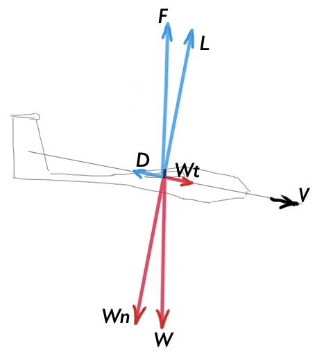
The weight $W$ of the glider has two components, $Wt$ and Wn. $Wt$ is in the same direction as $V$ and $Wn$ is perpendicular to $V$. Aerodynamic $F$ also has two components $L$ and $D$, where $L$ is perpendicular to $V$ and $D$ is parallel to $V$.
When $L = Wn$:
$Wt> D$, the linear acceleration of the glider is positive; $Wt <D$, the linear acceleration of the glider is negative; $Wt = D$, the linear acceleration of the glider is zero.
Some people think that there are only $L$, $D$, and $W$ on the glider. This is not entirely correct. Simply put, there are only two forces on the glider: one is aerodynamic $F$, and the other is gravity $W$. $L$ is only the component of $F$ in a direction perpendicular to $V$; $D$ is only the component of $F$ in a direction parallel to $V$. Some people think that $Wn$ does not exist, which is also incorrect. $Wn$ is the component of $W$ in a direction perpendicular to $V$; $Wt$ is the component of $W$ in a direction parallel to $V$.
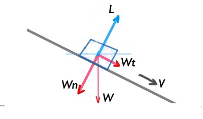
What pushes the block downward? $V$ is the speed at which the block moves downward. The weight of the block has two components: Wn perpendicular to $V$ and Wt parallel to $V$. $L$ is the reaction force of the slope (inclined plane) on the block. It is not the $L$ push block that moves downward, because $L$ has no component in the direction of $V$. Wt is the force that pushes the block downward.
-
$\begingroup$ Comments are not for extended discussion; this conversation has been moved to chat. $\endgroup$– foootCommented Mar 22, 2020 at 20:44
-
$\begingroup$ @enbinzheng while I think this is a good treatment of the general case where the glider is not necessarily constrained to be not accelerating, I do note that the original question said that the glider was not accelerating. But I hope you to decide to just leave this up as a good treatment of the general case rather than modify it in which case it would likely up just duplicating some of the other answers. $\endgroup$ Commented Apr 2, 2020 at 17:28


