I want to make a delta wing out of carbon fiber, but I do not know how many carbon fiber layers would be needed to prevent the wing from breaking due to shear stress. What would be the calculations and equations needed to find this out; which point is most likely to break? Sorry this question is devoid of details, I am quite lost when it comes to this.
-
$\begingroup$ Where do you imagine the shear stress will be? $\endgroup$– JimCommented Mar 22, 2022 at 19:22
-
2$\begingroup$ I think this is way too broad. A good answer to this question would basically teach you a course in structural mechanics and maybe a course on composite materials. That's a few hundred hours of study load. You could try some textbooks, e.g., Mallick: Fiber Reinforced Composites (no affiliation, just a book I happen to own). $\endgroup$– SanchisesCommented Mar 22, 2022 at 19:51
-
1$\begingroup$ Is this wing unique in shape and size? If so you might be able to duplicate the work others have already done. If not, build the wing with one layer of CF, then test to failure. Keep adding layers of CF until you achieve the strength you need. $\endgroup$– RetiredATCCommented Mar 22, 2022 at 19:55
2 Answers
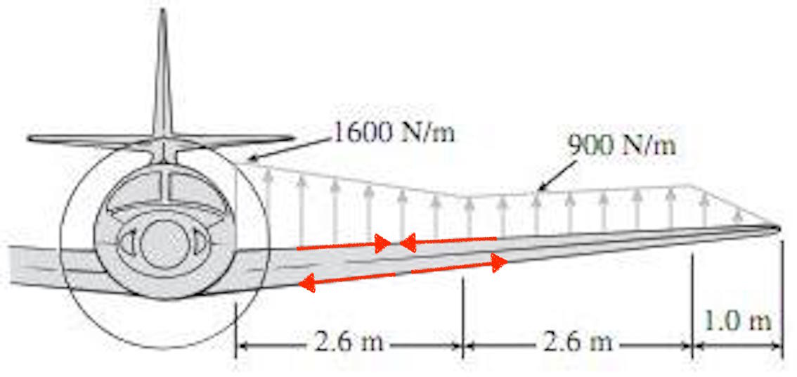
 Image source: modified from chegg.com. Picture earlier used in this answer
What is required is dimensioning the load, then the material placement and thickness.
The load. In a cantilever wing, the load in flight is at the wing root, caused by the lift. So the being moment upwards is the integrated lift distribution from wing tip to root, dimensioned for the highest load factor, in both an upwards and a downward direction (inverted flight). This wiki contains some regulation limits:
- For transport category airplanes, from −1 to +2.5 (or up to +3.8 depending on design takeoff weight)[5]
- For normal category and commuter category airplanes, from −1.52 to +3.8[6]
- For utility category airplanes, from −1.76 to +4.4[6]
- For acrobatic category airplanes, from −3.0 to +6.0[6]
The complete integrated lift load must be compensated for by a shear load downwards at the wing root.
There is a twisting load as well, probably not an ultimate load in a low aspect ratio delta wing.
Material placement. As can be seen in the pic, the wing bending moment is counteracted by a compression load in the upper skin and a tension load in the lower skin. The wing skins would need to be placed a fair bit apart, without causing strife with the aerodynamicists. A support structure that keeps the skins apart is a must, depending on the size of your craft could even be a honeycomb. Reduced wing thickness towards the tip is a good idea to save weight.
Carbon fibre layers. As many as required to absorb the loads found from points 1. and 2., dimensioned for skin buckling.
I want to make an airplane out of paper. The delta is the best choice, one of the strongest and easiest airfoil shapes to make. Very good for low wing loading, does not lift as well as a straight wing. Good stall characteristics.
I want to make a suspension bridge out of carbon fibre. Good for cables, but too flexible to keep the bridge from swaying.
You need to combine the carbon fiber with a stiff, but light material, such as balsa!. Carbon fibre "sandwiches" can be had at your local hobby shop and are amazingly strong.
If in doubt, build some models and analyze the effect of extreme loading (with weights), then do your delta wing scale- up. Other platforms may be tried as well.
