18
$\begingroup$

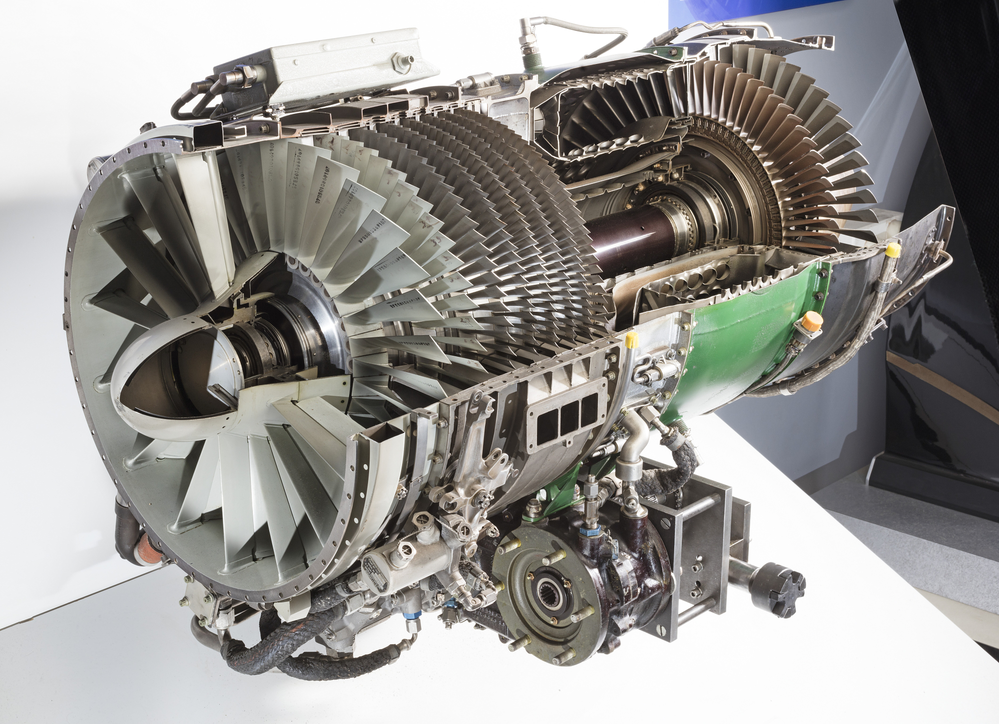
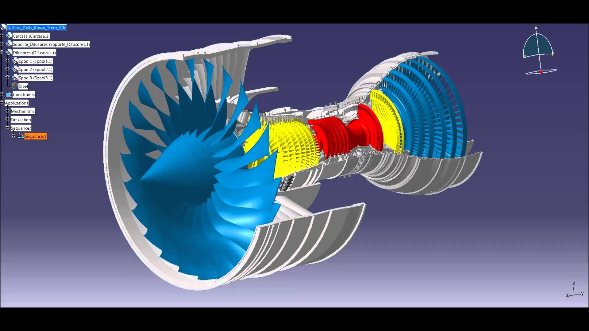
In almost every large turbofan I see, the LP turbine stages outnumber the HP turbine stages by a factor of at least 2. Here's a photo of the RR Trent 900:

enter image description here

The Trent 900 (like most Rolls-Royce turbofans) is a 3-spool turbofan, rather than a 2-spool. But even here, my observation holds. There are far more LP turbine stages than the middle or high pressure stages.

Why is this?

$\endgroup$
0

6 Answers 6

24
$\begingroup$

Because the LP turbine extracts power for the fan, which requires the most power. The HP and IP turbine only extract power for their connected compressors - the LP turbine extracts power for the fan and the LP compressor. The fan does work on all airflow through the engine, the compressors only on a fraction (10:1 for a high bypass like the Trent 1000). The fan produces up to 75% of the thrust of the engine.

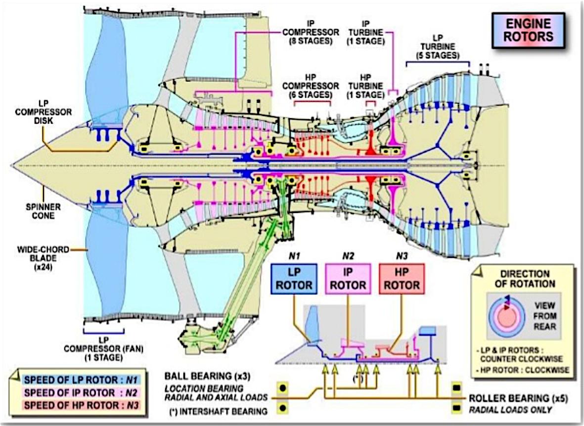
From this presentation: the cross section of the Trent 1000. It shows that the LP, IP and HP rotors have different rotational speeds, but does not list them. Another (older) presentation lists them as 3600. 6800 and 10200 RPM. Rotational speed goes down as the volume of the mass stream goes up.
enter image description here

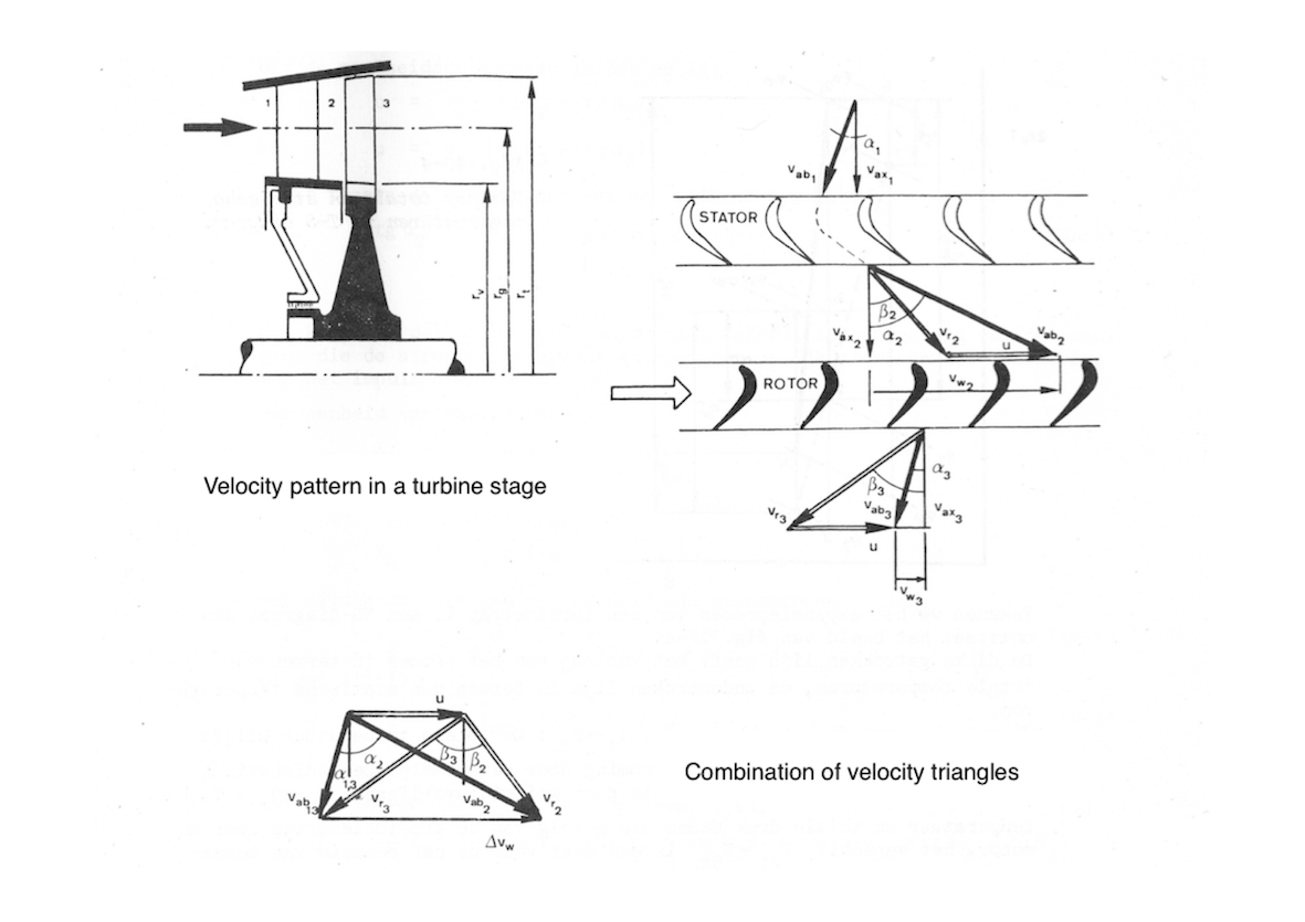
An old textbook of mine gives the power P extracted from a turbine stage as:

$$ P = \dot{m} \cdot u \cdot v_{ax} \cdot [tan (\alpha_2) + tan (\alpha_3)]$$

with

  • $\dot{m}$ = mass flow [kg/s]
  • u = tangential blade velocity [m/s]
  • v$_{ax}$ = axial gas velocity [m/s]
  • $\alpha_2$ and $\alpha_3$ angles according to the figure below.
enter image description here

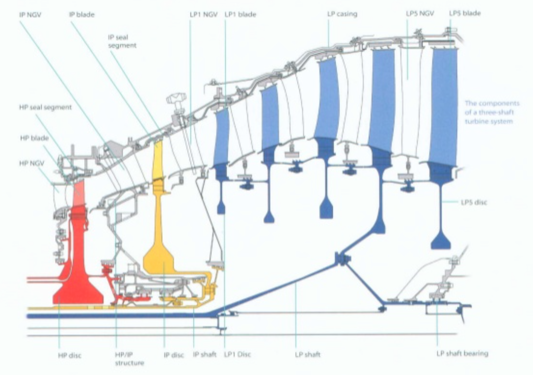
So the tangential speed of the turbine blade is in the equation for power extraction, which is composed of rotational velocity and blade radius. The faster the turbine turns, the more power can be extracted per stage, and the fewer stages required. Why then does rotational velocity go down with pressure? (HP = 10,200; IP = 6,800).
enter image description here

The reason is the constructional limits of the turbine. As the gas stream expands, the turbine blades become larger and are mounted at a greater axial distance, which results in greater centrifugal forces which are proportional to blade mass, rotational speed and distance from the axis. In order to limit centrifugal forces, the rotational velocity of the rotor is reduced: each subsequent stage turns at a lower RPM. Notice that a lower RPM can be compensated by mounting the blade further away from the rotational axis.

The LP rotor of an un-geared engine runs at the same rotational velocity as the fan. Its optimal RPM for the turbine may be higher, and that can be accommodated by the geared fan. As the bypass ratio gets higher, the LP turbine will be extracting a higher fraction of total power from the airstream - turboprops and turboshafts have a gearbox in between the LP shaft and the propeller/rotor, and the high bypass fan approaches the relative dimensions of a propeller...

$\endgroup$
6
  • $\begingroup$ Interesting but in this case, with 3 spools, this begs the question of why not balance the stages more? Like put 1 or 2 for the fan on the first spool, 1 or 2 for the smaller LP compressors, and 1 or 2 for the HP compressors. Instead the LP compressors have by far the most stages and are only powering the fan, which to my knowledge is just the lowest of the LP compressors. $\endgroup$
    – DrZ214
    Commented Sep 6, 2017 at 9:19
  • $\begingroup$ The IP and HP spools spin faster than the LP spool. $\endgroup$
    – Koyovis
    Commented Sep 6, 2017 at 9:23
  • 1
    $\begingroup$ @DrZ214 That's the very point of a multispool engine: to have the fast components on fast spools and slow component on a slow spool. What you propose is pretty much single-spool engine, proven to be not the best solution. Turbofans are difficult to understand, because the difference between fan and compressor appears blurred. Start at turboprop or shaft engine, there you get clear-cut distinction between driving fast-spinning internal components (compressors) and a slow-moving external component. Fan is little more than a prop mounted in same casing. Fan is not a compressor stage. $\endgroup$
    – Agent_L
    Commented Sep 6, 2017 at 14:33
  • 1
    $\begingroup$ You might want to add that the HPT is working in much denser air. For a compression ratio of 40:1 the density change is about 14. If the last stage of the LPT expands air down to ambient pressure, the HPT needs only 7% of the blade area for the same power extraction. $\endgroup$ Commented Sep 6, 2017 at 19:04
  • 1
    $\begingroup$ :) Yes indeed, the radius should be constant. It's the tangential speed of the blade at mid point, taken as the average, have corrected. $\endgroup$
    – Koyovis
    Commented Sep 7, 2017 at 8:14
9
$\begingroup$

The answer provided by Daniel Kiracofe is correct, I just have a couple of additional comments and I don't have enough reputation to add this as a comment to his answer.

  1. On high bypass engines, the speed of the LP rotor is usually limited by the tip speed of the fan due to its large diameter.

  2. One of the first determinations in choosing between a geared and a non-geared (conventional ) design is to make sure you can remove at least as much weight from the LPT as you are adding with the gearbox. If you can't, then the geared design is not a viable option.

$\endgroup$
1
  • $\begingroup$ Can you provide a quantification or a reference for your claim? $\endgroup$
    – Koyovis
    Commented Sep 7, 2017 at 6:57
7
$\begingroup$

Here's an even more interesting question. Take a look at the P&W geared turbofan cross section (e.g. this article). It only has three LPT stages! So how come the GTF has 3 and all of the other engines like the RR Trent 900 have a lot more? (e.g. a GE90 has like 6 or 7).

The answer is this: fans are best when they run slowly. LPTs are most efficient when they run quickly. On an engine like the Trent 900 or GE90, the fan and LPT are on the same shaft, so they have to run at the same speed. So you have to compromise. Usually the compromise tends to favor the fan. So, because the shaft is running at the speed that the fan wants to run at, the LPT is inefficient. That is: each LPT stage is not extracting much power from the air. Therefore, to get out the total power that you need, you have to have a lot of LPT stages.

Now, on a geared turbofan, there is gearbox between the fan and LPT. That means that the fan and LPT don't have to run at the same speed. The fan can run slowly like it wants to, and the LPT can run fast, like it wants to. In that case, the LPT is much more efficient, and you need only a few stages.

$\endgroup$
2
  • $\begingroup$ The geard turbofan still requires 3 stages, as opposed to 1 stage for IP and HP.. $\endgroup$
    – Koyovis
    Commented Sep 6, 2017 at 15:59
  • 1
    $\begingroup$ And an even more interesting fact: the P&W geared turbofan is used on the A320Neo. The Trent 1000 powers the B787, a much larger aircraft. Much more power to extract for the much bigger fan. $\endgroup$
    – Koyovis
    Commented Sep 7, 2017 at 6:57
4
$\begingroup$

In addition to Koyovis' answer which discusses the output requirements of the turbine stages, there's an input issue as well:

The HP turbine stage has the best spot: it has the highest input pressure, so you only need one stage to extract enough power to run the HP compressor. The LP turbine stages run on exhaust gases that have already had some energy extracted from them, so lower pressure->stage is less efficient->you need more of them to get the required power.

$\endgroup$
3
$\begingroup$

I like some of the answers here, but none seem to answer the question from the fluid mechanics' perspective.

One of the reasons the low pressure region has more stages is because you want to avoid flow separation which cause a loss of energy to recirculation instead of providing thrust or power. The low pressure region is compressing; this causes an adverse pressure gradient. In layman's terms, the flow basically wants to go backwards because high pressure tends to flow towards low pressure.

The turbine blades have airfoil shapes, and they work exactly like aircraft wings in that lift is produced in one rotational direction to produce a desired effect. Therefore, if you try to turn the flow too drastically without considering the adverse pressure gradient, then you will get flow separation and a drastic drop in your compression ratio and a drop in efficiency for all of the other turbine parts.

Turbomachinery designers want to turn the flow a certain amount, but they do not want to do it with one stage. So, the engineers opt to turn the flow a little bit each during each stage, and it turns out that the extra weight from all of that metal is worth it.

On the flip side, the high pressure section has fewer blades because the flow really wants to just leave already, so recirculation is much less likely. This is where you can cut corners and put half as many stages. Look how drastic the flow turning is on this high pressure turbine blade here. http://www.technology.matthey.com/wp-content/uploads/articles/39/3/pmr0039-0117-f2.gif

Now that you have seen the high pressure blade, take a look at these low pressure blades.

See how the low pressure blades are almost straight?

https://en.wikipedia.org/wiki/Flow_separation

$\endgroup$
1
  • $\begingroup$ that watermark makes me think that you cannot post that image here. $\endgroup$
    – Federico
    Commented Sep 7, 2017 at 16:58
1
$\begingroup$

For Two specific reasons.

  1. Higher power off take - LPT drive LPC and Fan together in 2-spool and GTF architecture (and only Fan in 3-spool architecture). In any case the Fan alone or Fan + LPC will take up significant portion of the total work input. Thus high mechanical power needs to be extracted by the LPT.
  2. Lower RPM: But perhaps the more important factor is except in GTF, the LPT are run at very low speed compared to the HPT at which they work sub-optimally. Thus energy extraction per stage is reduced significantly. Hence more number of stages needed. As already pointed out in another answer, since GTF removes this restriction, the PW1000G engine needs only 3 LPT stages as now they rotate at ~10000rpm instead of ~3500rpm for other engines.
$\endgroup$

You must log in to answer this question.

Not the answer you're looking for? Browse other questions tagged .