Good answers have been posted, but here is another spin that adds a few other important points, while omitting for brevity some of the other points that have already been made. This answer also clears up a misconception in the original question about the significance of the Lift/Drag ratio in relation to the airspeed for best glide ratio and the airspeed for minimum sink rate.
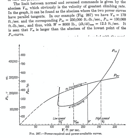
For unpowered flight, we can draw a curve of sink rate versus forward (horizontal) speed. (Some other answers have referenced this as a "power curve".)
In unpowered, non-turning flight, Lift, Drag, and Weight form a closed vector triangle. Since the Lift and Drag vectors act perpendicular and parallel to the flight path, respectively, this closed vector triangle "anchors" the direction of the flight path in space with respect to the Weight vector. In other words, if we know the direction of the flight path with respect to the ground-- i.e. the glide angle-- then we know the L/D ratio, and vice versa. In fact, in unpowered, non-turning flight, the glide ratio (horizontal distance travelled per unit of altitude lost) is always exactly the same as the Lift/ Drag ratio. This means that glide angle = arctan (D/L).
This means that the smallest (i.e. flattest) glide angle takes place at the minimum D/L ratio.
Starting with a graph of sink rate versus horizontal (forward) speed, there's an easy way to find the "glide ratio", or horizontal distance traveled divided by altitude lost, for any given horizontal speed. It's simply the slope of the line drawn from the origin of the graph to the point in question. The highest possible "glide ratio"-- which corresponds to the smallest possible "glide angle"-- is simply the point where a line drawn in this manner is exactly tangent to the curve of sink rate versus forward (horizontal) speed. And as we've already noted, in unpowered flight, the "glide ratio" at any given forward (horizontal) speed is also exactly the same as the L/D ratio at that speed, so the highest possible glide angle also occurs at the forward (horizontal) speed that gives the highest L/D ratio or lowest D/L ratio.
Note that this tangent point will always occur somewhat to the right of the point of minimum sink rate. The speed for the flattest glide angle (best glide ratio) is always somewhat faster than the speed for the minimum sink rate.
For reasonably flat glide angles, forward (horizontal) speed is nearly the same as airspeed. Therefore, for most practical purposes, our graph of sink rate versus forward (horizontal) speed can be re-labelled as a graph of sink rate versus airspeed.
Recall again that the smallest (i.e. flattest) glide angle takes place at the minimum D/L ratio. For reasonably flat glide angles, as we vary airspeed, lift remains nearly equal to weight, so nearly all the variation in the L/D ratio (i.e. the glide ratio) is due to variation in Drag, not Lift. (Don't misinterpret this to mean that the lift coefficient stays nearly constant as the airspeed varies-- it does not.) This means that for reasonably flat glide angles, it is a close approximation of reality to say that the airspeed that yields the minimum D/L ratio and the smallest (flattest) glide angle, is also the airspeed the yields minimum Drag force, as measured in pounds or Newtons. (Don't misinterpret this to mean that the drag coefficient is minimized at this airspeed-- it is not.)
Therefore, at the forward (horizontal) speed, and the airspeed, that yields the minimum sink rate, the Drag force is actually higher than it is at the airspeed that yields the maximum glide ratio (minimum glide angle). Here's one way to think about this-- loosely speaking, the Drag force determines the steepness of the "slope" that the aircraft is gliding down. But travelling more slowly along a slightly steeper slope will give a lower rate of descent than travelling more quickly along a slightly flatter slope.
What happens if we start with a sink rate-versus-airspeed curve generated by an aircraft with the prop removed, or with the engine generating just enough power so that the prop is contributing exactly zero net thrust, and then we change the conditions so that the prop is windmilling and forcing the engine to turn? The sink-rate-versus-airspeed curve will be degraded-- the sink rate for any given airspeed will be increased, but more so at higher airspeeds.
The point of minimum sink rate, and the point of flattest glide, will both be shifted toward the left, toward lower airspeeds.
To maintain level flight, the motor has to supply enough power to offset the sink rate that the aircraft would experience if the motor were contributing zero net thrust. More precisely, the power requirement is equal to sink rate times weight. Therefore our graph of sink rate versus airspeed can also be thought of as a graph of "power required" versus airspeed. However, to look at how an aircraft will perform when we add power, the appropriate "power required" graph would be one generated with the propeller removed (or with just enough engine power applied to produce exactly zero thurst), not one generated with the propeller windmilling.
At any given airspeed and throttle setting (e.g. wide-open throttle), the sink rate or climb rate will be due to the difference between the "power required" and the "power available". At the wide-open throttle position, if the graph of "power available" versus airspeed were a simple horizontal line, then the shape of the "power required" graph-- which is the sink rate versus airspeed graph-- would entirely determine the the airspeed for maximum climb rate. In this case, the maximum climb rate would always occur at the power-off minimum sinking speed-- at least so long as we were talking about a sink rate versus airspeed graph that was created with the prop removed or idling in the zero-thrust condition, rather than windmilling.
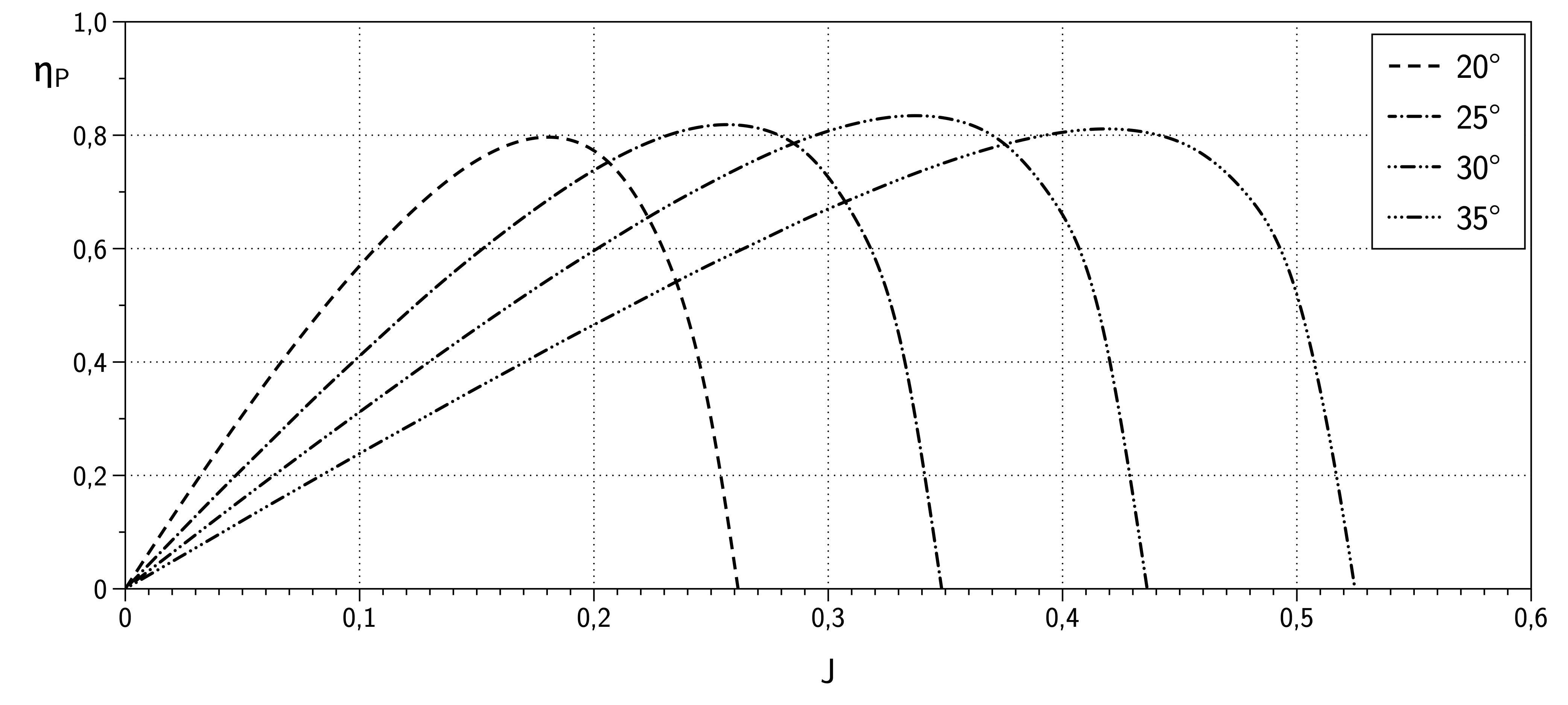
However, the shape of the power-available curve is not a simple horizontal line, especially in the case of an aircraft with a fixed-pitched prop. It will typically have a peak that is located well to the right of (i.e. higher than) the airspeed for the best glide speed or max L/D ratio, which biases the speed for best climb rate toward a higher airspeed.
In summary, the best climb rate occurs at a higher airspeed than the flattest glide angle because--
1) the airspeed for flattest glide angle is measured with the prop windmilling, not with the engine applying just enough power to generate a zero-thrust condition. This shifts the sink rate-versus-airspeed curve toward the left of where it would be if it were generated with the motor creating just enough power so that the prop were contributing neither thrust nor drag.
and
2) the power-available versus airspeed curve is not a flat horizontal line, but rather peaks at an airspeed that is higher than the airspeed corresponding to the flattest glide angle. With a fixed-pitch prop, this is typically is true even if we are making a comparison to the aircraft's performance at the airspeed that gives us the flattest glide angle with the engine providing enough power to generate a zero-thrust condition, and it is even more true if we are making a comparison to the aircraft's performance at the airspeed that gives us the flattest glide angle with the engine windmilling. This biases the best climb-angle and best climb rate airspeeds toward the right (toward higher airspeeds) compared to what we'd see if the propulsion system delivered the same amount of power at all airspeeds.
Two final notes--
A) All discussions of glide angle in this answer are with respect to the airmass, not the ground. In other words, if we're measuring our glide angle with respect to the ground, then we're doing so in zero-wind conditions. Optimizing the choice of airspeed to fly to get the best possible glide angle over the ground various wind conditions is an interesting topic, but one that is beyond the scope of this answer.
B) This answer has only touched briefly on the subject of lift and drag coefficients. It may interest the reader to know that the following are true, using "Cl" to represent the lift coefficient and "Cd" to represent the drag coefficient:
i. The airspeed for max L/D ratio is also the airspeed where the ratio of Cl/Cd is maximized.
ii. The airspeed that yields the minimum sink rate is also the airspeed that yields the maximum value of (Cl cubed) / (Cd squared).
iii. The expressions (Cl/Cd) and (L/D) are equivalent, but the expressions ((Cl cubed) / (Cd squared)) and ((L cubed) / (D squared)) are not equivalent.


