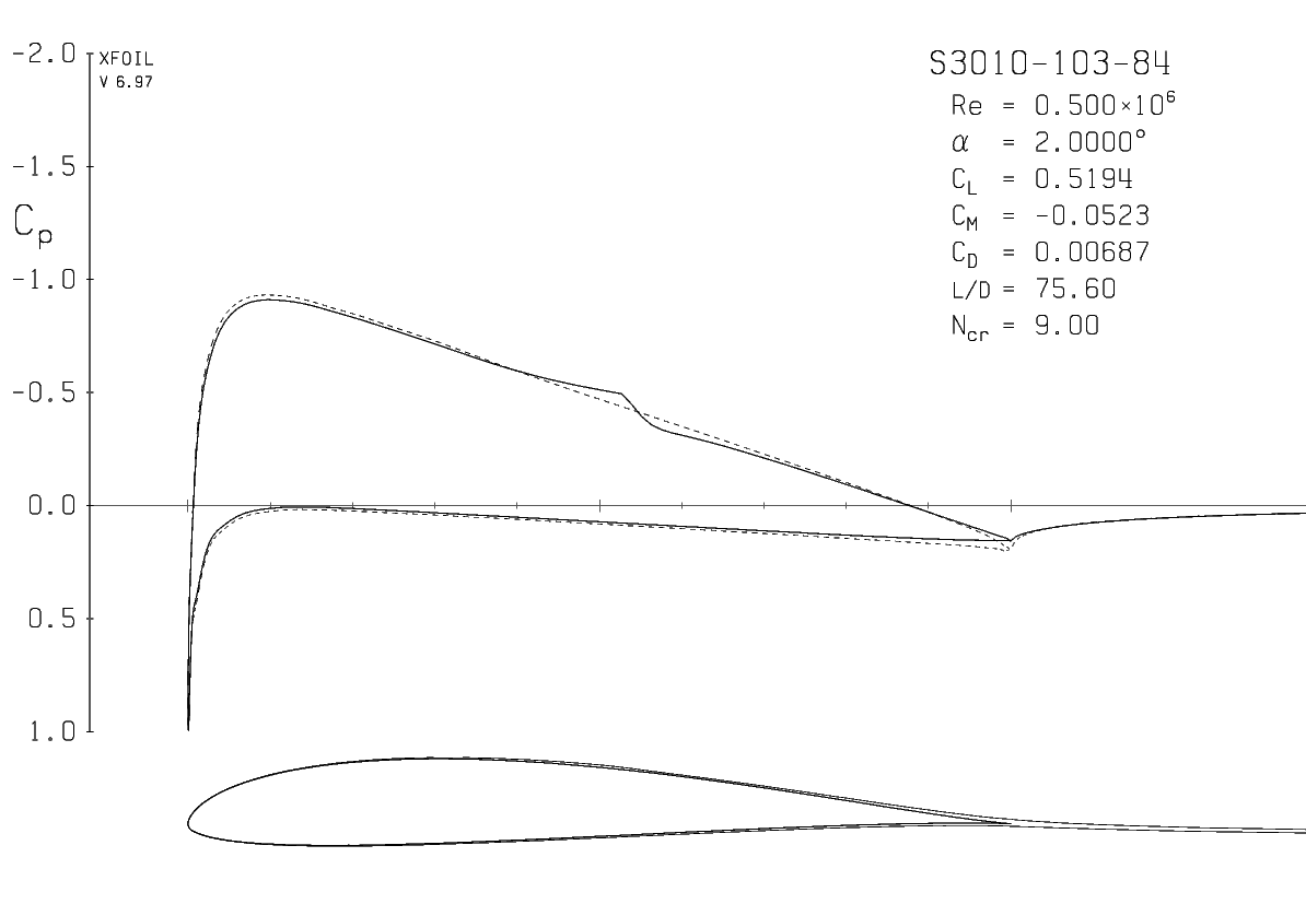
The velocity-jump at $\simeq 0.5c$ is due to a laminar separation bubble.
But you ask two different things here:
- Prevent leading edge separation
A leading edge separation may happen as the laminar separation bubble progresses forward for higher angles of attack and is more common in thin airfoils. A way to suppress this is by the use of roughness elements, a trip or vortex generators. You can experiment with this using Xfoil and fixing the transition location at the point (or in a distance before this point) that you assumed that you have a roughness element for example. Otherwise try modifying the geometry with Xfoil's inverse design routines and if you're seriously into this read these Low Reynolds
Number Airfoil Design Lecture Notes provided by Selig.
- Increase aerodynamic efficiency ($L/D$)
Increasing $L/D$ for a specified angle of attack for these kind of airfoils and for the low-Reynolds regime, means in general to reduce the velocity-jump of the laminar separation bubble. If I am correct, Selig's airfoils are already an improved version of similar NACA airfoils for low-Re. To do this you should again consult the aforementioned notes.
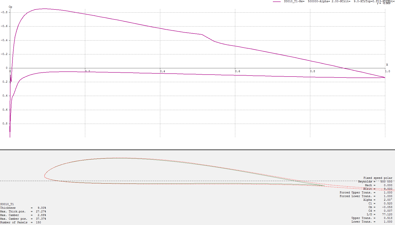
Are you sure that the spike on $c_p$ plot before the suction peak is not a paneling issue? It seems unphysical. Have you tried refining your airfoil? I do not capture this with the same analysis using Xfoil with 200 panels.

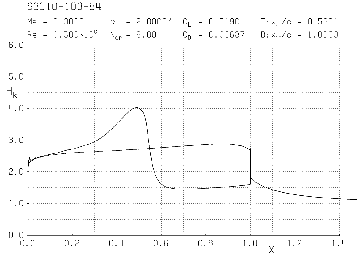
A rule of thumb is that the shape parameter ($H_k$) of the boundary layer at a laminar separation bubble is around 4. You can see from the following plot that you have a laminar separation bubble around $0.5c$ on the upper surface. Not in the leading edge though.


