AC to AC conversion with frequency change from 400 Hz to 50/60 Hz is obtained by transforming AC to DC first (usually to 28 VDC to be compatible with batteries) and then using a static power inverter to convert from DC to AC. The inverter performs the voltage transformation in the same step.
From an EASA certification perspective, electricity quality is measured at the output of static power inverters.
The requirements are described in ETSO-C73, with an exception about the frequency, as for passenger outlets the frequency must be 50 Hz or 60 Hz, depending on countries, instead of 400 Hz. This exception is described in this document:
Deviate from ETSO-C73 attached FAA Standard for Power Inverters
paragraph 2.3 and provide 50 Hz +/-1 % or 60 Hz +/-1 % instead of the
required 400 Hz.
ETSO-C73 itself refers to FAA requirements:
2.3 Frequency: The frequency of the inverter under all conditions of
load and test environment shall be 400 cycles per second ±1 percent
at the input voltages specified in 2.2a. and 2.2b.
2.4 Voltage Output: The average phase output voltage, under the
conditions of input specified in 2.2a. and 2.2b. and under a ll
conditions of test environment, shall be 115 volts a.c. +5 percent -7
percent
2.5 Waveform: The output waveform shall be substantially sinusoidal
and contain less than 7 percent harmonic distortion under
all load conditions not exceeding 110 percent rated output.
What does that mean?
Voltage value tolerance +5%/-7%. This is pretty nice and equivalent to what we have at home in industrialized countries. I addition, common devices are very tolerant to voltage variation, as they are simple to eliminate using a high value capacitance.
Frequency tolerance ±1% means ±0.5 Hz. Most, if not all, devices don't rely on a very stable grid frequency. It was the case of first digital clocks to save the price of a crystal oscillator, but now crystals and PLL are used everywhere when a stable clock is required.
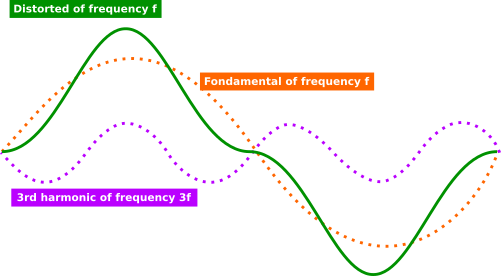
Waveform with a maximum of 7% harmonics. This is the usually the most important tolerance. It describes how much the voltage wave can differ from a pure sine wave.
Any periodic wave of frequency f which is not exactly sinusoidal can be broken down into a set of pure sine waves which frequencies will be f, 2f, 3f, 4f, etc, and inter-products. Breakdown is obtained by a Fourier analysis. The multiples of f are named harmonic frequencies, and in practical this is the same as if there was multiple mono-frequency generators.
Some of those frequencies can interfere with receivers or disrupt other circuits due to impedance changing with frequency. In this case the amplitude of the harmonics must be weaker than 7% of the fundamental wave.

For the power grid where I live:
- Voltage tolerance is ±10%
- Frequency tolerance is ±1%.
- For harmonics, this is more complex as the customer's load affects harmonics, there are mutual commitments which are respectively for 2nd, 3rd, 4th, 5th, 7th orders: 2%, 5%, 1%, 6%, 0.5%, 5%.
USB sockets voltage is defined in the USB standard:
- 5V +0.25V/−0.55V (+5%/-10%) for USB 3.
There is no difficulty to obtain it from any DC source to minimize conversion stages, losses and heat. This can be done by a push–pull converter. USB power is likely obtained from 28 VDC.

