6
$\begingroup$

The pitot tube is used to measure the air pressure later converted into air speed. However air pressure varies according to several elements, including the location related to the wing:

enter image description here
(Source: av8n.com)

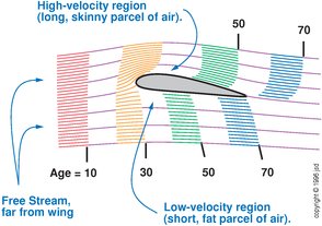
On one hand the probe, depending on its location, could measure the pressure in the free stream, in the high velocity stream, or in the low velocity stream.

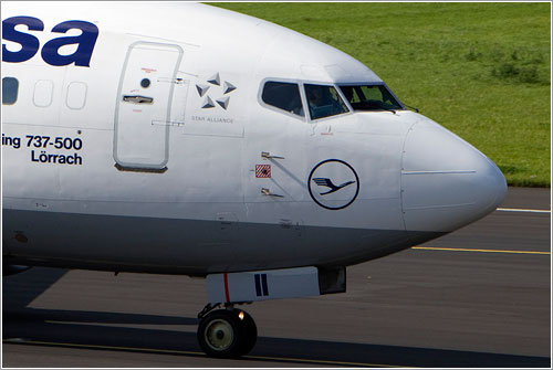
On the other hand, pitots are found at various locations, e.g:

enter image description here
On the fuselage, far from the wing, B-737 (source)

enter image description here
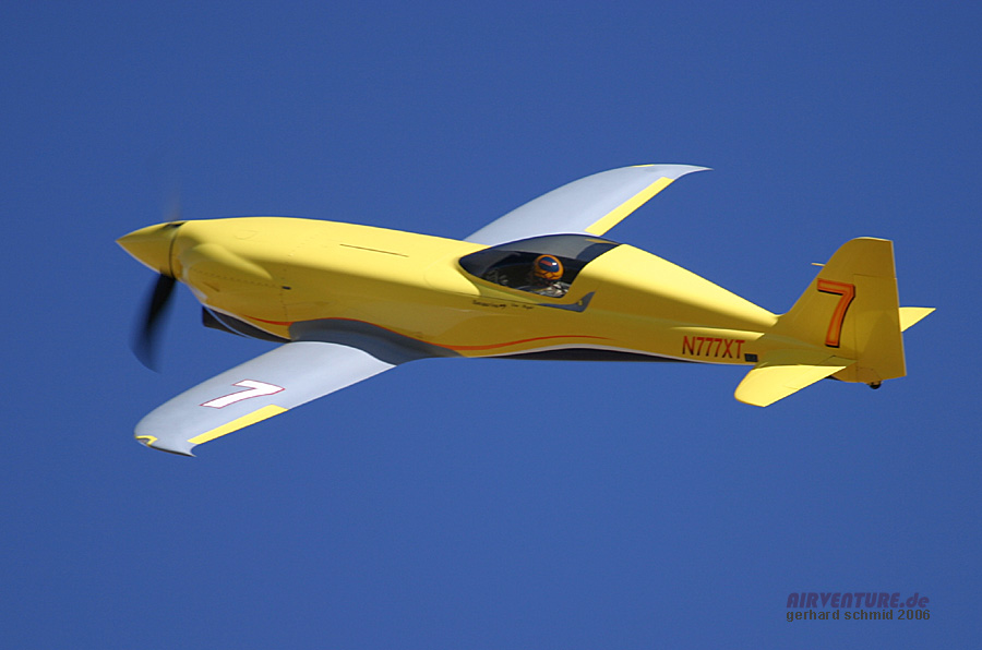
On the vertical stabilizer, kit Nemesis NXT (source)

enter image description here
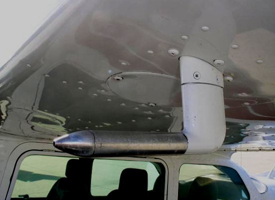
Under the wing, Cessna 172 (source)

Furthermore when the probe is fixed to the fuselage or to the stab, depending on the angle of attack, it can be rotated into the slowed down or the accelerated portion of the stream.

Can you shed some light on what is usually measured by the pitot? Does the pitot indicate different pressures if placed in the different stream areas (free, accelerated, decelerated)? If so:

  • What is usually measured by the probe?
  • What is usually displayed on the speed indicator?

Edit: While I needed to select a single answer, several other answers contain additional interesting elements and deserve votes as well.

$\endgroup$

4 Answers 4

8
+100
$\begingroup$

You're correct that there are a number of parameters that influence the measurement of air data in general. For example, the total pressure measurement (as done using the Pitot tube) is influenced by,

  • Angle of attack
  • Reynolds number
  • Mach number
  • Velocity gradients
  • Proximity to surfaces (wings, fuselage etc.)
  • Flow steadiness
  • Probe geometry
  • Compressibility and shock
  • Shape of the measuring head etc.

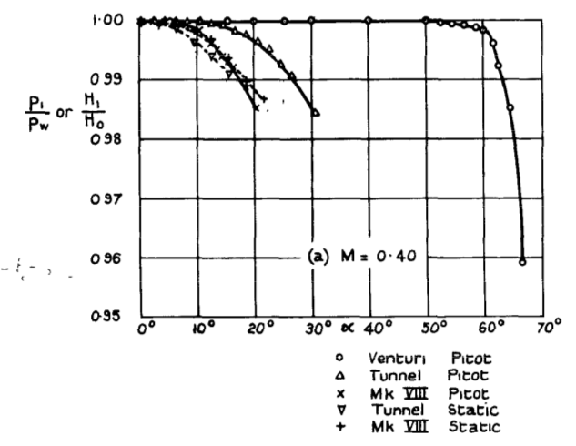
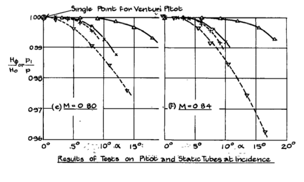
In case of total pressure, as long as the (pitot) tube is outside the boundary layer and the flow angle is less (<10% usually), the error is negligible. The following image shows the error due to incidence angle at different speeds for different head designs. Here, $H_{0}$ is the Free stream total head es measured in the tunnel intake and $H_{1}$ is the head measured by the instrument.
M-0.4 Pitot

M-0.84 Pitot

Image from Tests on the Effect of Incidence on some Pressure Heads at high Subsonic Speeds by E W. E. Rogers, D.I.C., & SC and C. J. Berry,

From the same paper:

Tunnel measurements have shown that up to at least M = 0.75 the loss in total head on a Venturi-shrouded pitot was less than 0.5% for incidences of up to about 40$^{\circ}$. This compares with a limit of 9$^{\circ}$ at M = 0.7 to 0.85 for 0.5% loss on the pitot section of a standard Mk.VIIIA instrument and 17$^{\circ}$ at M = 0.7 to 0.9 on the small pitot heads in general use ...

Static pressure measurement errors are similar; however, there are some points where the errors in static pressure measurement in the fuselage of the aircraft are minimal and the static ports can be mounted at these points (in addition to the static port in pitot-static tube).
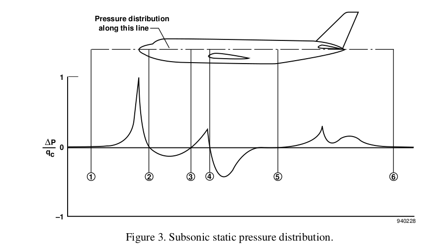
Static Pressure Points

Image from Airdata Measurement and Calibration by Edward A. Haering, Jr. NASA Dryden Flight Research Center

It would be better if the static ports are mounted at these points in order to reduce the error.

From the above data, it can be seen that for GA and commercial aircraft, the position of the pitot-static tube can be located with reasonable accuracy at a number of points as long as it is in the undisturbed flow.

Another point is that the pitot-static tube measures pressure and the Air Data Computer (usually) converts it into the required parameter (for eg. speed). So,if the errors are known (during flight testing, for example), the instruments could be calibrated as per requirements. In general, typical methods used for calibration are,

  • Tower Flyby
  • Trailing Static or Trailing Cone
  • Pacer Aircraft
  • Radar Tracking
  • Dynamic Maneuvers

among others. Other electronic methods are also used for calibration purposes.

In order to achieve the very high accuracy required during flight testing and to serve as a reference, air-data booms are sometimes used in experimental and test aircraft, as can be seen in the F-35 below, whose data can be used for calibration.
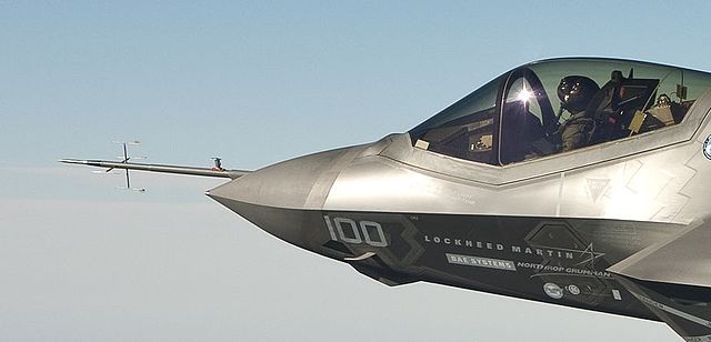
F-35

"Cockpit and Air Data Boom F-35C" by File:CF-1 flight test.jpg: Andy Wolfederivative work: Berg2 (talk) - File:CF-1 flight test.jpg (cropped). Licensed under Public Domain via Wikimedia Commons.

In some extreme cases, the nose mounted airdata systems which are typically used (to minimize influence of aircraft on measurements) can be unsuitable due to specific reasons. A good example is the NASA F-18 High Alpha Research Vehicle (HARV) program, where,

... a noseboom was deemed unacceptable for this program. At high angles of attack, the noseboom has a significant effect on the forebody aerodynamics and thus on the stability and control of the aircraft. As a result, wingtip mounted sensors and a flush nose-cone mounted sensor were used.
$\endgroup$
3
  • $\begingroup$ Do probes on the three examples in my question measure the actual free air stream speed (pressure)? $\endgroup$
    – mins
    Commented Jan 17, 2016 at 15:41
  • $\begingroup$ @mins, it does not measure speed at all. It is not intended to! The "indicated speed" is really dynamic pressure and this is intentional, because lift depends on dynamic pressure, not speed. It is just expressed as speed it would correspond to at specific conditions (101.325 kPa and 15°C). $\endgroup$
    – Jan Hudec
    Commented Jan 17, 2016 at 21:55
  • $\begingroup$ @mins, AFAIK the B737 has static port and appears to be placed in the point 2 on the pressure distribution diagram to minimize error. The C172 one does not seem to have static port and as explained above, the total pressure is the same anywhere outside the boundary layer; the error depends on how well the static port is placed. The middle one is probably similar case with separate static port. $\endgroup$
    – Jan Hudec
    Commented Jan 17, 2016 at 22:01
8
$\begingroup$

The first thing to have in mind is that a pitot tube is NOT measuring speed: the pitot tube measures pressure and later on the airplane (flight management system in a modern airplane) calculates the speed based on pressure.

More specifically the pitot tube calculates the stagnation pressure which is the sum of static pressure (what you show in your picture) and the dynamic pressure (pressure obtained by stopping the air).

The total pressure remains constant in the external free flow in normal airplane operations BUT will not remain constant in the boundary layer, which is a small region close to the wall. The boundary layer grows with the distance downwash along the airplane.

What I explained here justifies the following design solutions:

  • Pitot tubes are usually installed with an small distance to the walls "like floating" in order to be outside the boundary layer and free of loses on the stagnation pressure.
  • Pitot tubes are never installed at the tail of the airplane, in order to avoid high thickness of boundary layer (could reach 1 meter).
$\endgroup$
3
  • $\begingroup$ Essentially C-172 is having the probe located in the very beginning of the wing, not contaminated by any boundary layer, the nemesis has it on the tip of the vertical plane, also avoiding the boundary layer of the fuselage. Notice that you put on the table 2 airplanes with propelers, the pitot needs to be far for the properler downwash to avoid interference. $\endgroup$ Commented Jan 17, 2016 at 15:42
  • $\begingroup$ What they measure is the total pressure. Meanwhile the airflow is not disturbed by the boundary layer does not mind is decelerated or accelerated. Is almost impossible to introduce it at undisturbed flow except by setting the pitot in the front of the fuselage $\endgroup$ Commented Jan 17, 2016 at 21:13
  • 1
    $\begingroup$ Pitot tubes are often installed at the tail on gliders! $\endgroup$
    – Andrius
    Commented Jan 19, 2016 at 6:15
2
$\begingroup$

Speed indicator displays IAS(indicated air speed). It has all this position, installation, instrument errors. When you correct for these errors(using tables from aircraft manual) or air data computer you get calibrated air speed(CAS). Pitot position doesn't matter as it's compensated. High speed low pressure or low speed high pressure. Pressure inside the tube will be the same.

$\endgroup$
1
  • $\begingroup$ It does not vary. Look at en.wikipedia.org/wiki/Position_error and go Pitot system. You can think that position error in this case is compensated. If you get higher pressure you get lower speed. If you have higher speed you have lower pressure... So it doesn't matter where you put Pitot unless it's boundary layer. Boundary layer is effected by other forces like friction so you cannot put Pitot there. $\endgroup$
    – Andrius
    Commented Jan 19, 2016 at 6:08
0
$\begingroup$

This is a link to the Instrument Pilot handbook offered by the FAA: http://www.faa.gov/regulations_policies/handbooks_manuals/aviation/media/FAA-H-8083-15B.pdf

page 97 explains the pitot-static system. It is a simple answer with illustrations. It might not explain every nuance of the system, but it is enough for a pilot to pass his exam!

$\endgroup$
0

You must log in to answer this question.

Not the answer you're looking for? Browse other questions tagged .