You're correct that there are a number of parameters that influence the measurement of air data in general. For example, the total pressure measurement (as done using the Pitot tube) is influenced by,
- Angle of attack
- Reynolds number
- Mach number
- Velocity gradients
- Proximity to surfaces (wings, fuselage etc.)
- Flow steadiness
- Probe geometry
- Compressibility and shock
- Shape of the measuring head etc.
In case of total pressure, as long as the (pitot) tube is outside the boundary layer and the flow angle is less (<10% usually), the error is negligible. The following image shows the error due to incidence angle at different speeds for different head designs. Here, $H_{0}$ is the Free stream total head es measured in the tunnel intake and $H_{1}$ is the head measured by the instrument.
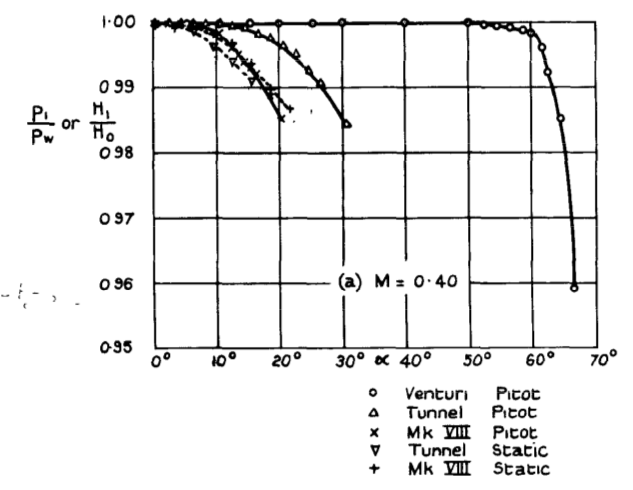
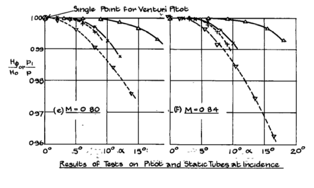
Image from Tests on the Effect of Incidence on some Pressure Heads at high Subsonic Speeds by E W. E. Rogers, D.I.C., & SC and C. J. Berry,
From the same paper:
Tunnel measurements have shown that up to at least M = 0.75 the loss in total head on a Venturi-shrouded pitot was less than 0.5% for incidences of up to about 40$^{\circ}$. This compares with a limit of 9$^{\circ}$ at M = 0.7 to 0.85 for 0.5% loss on the pitot section of a standard Mk.VIIIA instrument and 17$^{\circ}$ at M = 0.7 to 0.9 on the small pitot heads in general use ...
Static pressure measurement errors are similar; however, there are some points where the errors in static pressure measurement in the fuselage of the aircraft are minimal and the static ports can be mounted at these points (in addition to the static port in pitot-static tube).
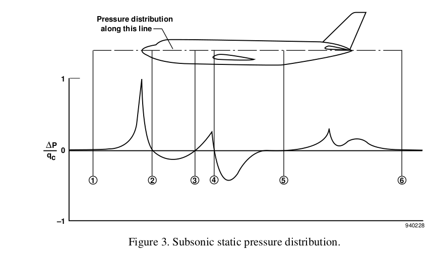
Image from Airdata Measurement and Calibration by Edward A. Haering, Jr.
NASA Dryden Flight Research Center
It would be better if the static ports are mounted at these points in order to reduce the error.
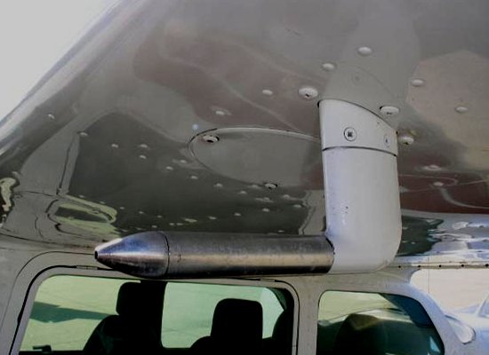
From the above data, it can be seen that for GA and commercial aircraft, the position of the pitot-static tube can be located with reasonable accuracy at a number of points as long as it is in the undisturbed flow.
Another point is that the pitot-static tube measures pressure and the Air Data Computer (usually) converts it into the required parameter (for eg. speed). So,if the errors are known (during flight testing, for example), the instruments could be calibrated as per requirements. In general, typical methods used for calibration are,
- Tower Flyby
- Trailing Static or Trailing Cone
- Pacer Aircraft
- Radar Tracking
- Dynamic Maneuvers
among others. Other electronic methods are also used for calibration purposes.
In order to achieve the very high accuracy required during flight testing and to serve as a reference, air-data booms are sometimes used in experimental and test aircraft, as can be seen in the F-35 below, whose data can be used for calibration.
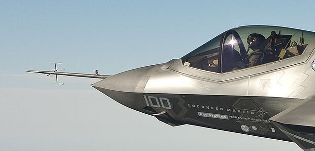
"Cockpit and Air Data Boom F-35C" by File:CF-1 flight test.jpg: Andy Wolfederivative work: Berg2 (talk) - File:CF-1 flight test.jpg (cropped). Licensed under Public Domain via Wikimedia Commons.
In some extreme cases, the nose mounted airdata systems which are typically used (to minimize influence of aircraft on measurements) can be unsuitable due to specific reasons. A good example is the NASA F-18 High Alpha Research Vehicle (HARV) program, where,
... a noseboom was deemed unacceptable for this program. At high angles of attack, the noseboom has a significant effect on the forebody aerodynamics and thus on the stability and control of the aircraft. As a result, wingtip mounted sensors and a flush nose-cone mounted sensor were used.
