2
$\begingroup$

Study of countless aerodynamic questions and answers on this site has reshaped my understanding of both lift and and induced drag.

Questions like this: How does an aircraft form wake turbulence? have gone a long way to redirecting understanding about how induced drag works as well as what the wingtip vortices are, and most importantly, are not.

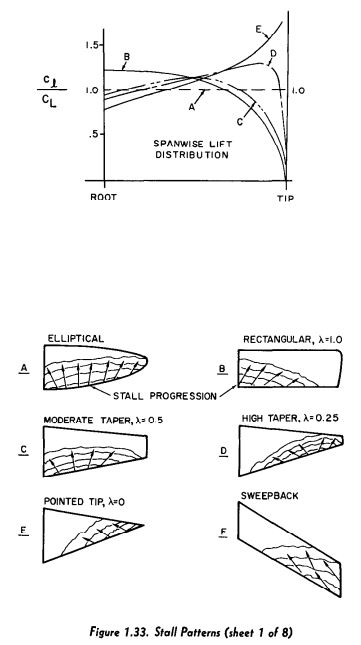
Study of the Aerodynamics for Naval Aviators text shows the various lift distribution and therefore stalling profiles of each wing planform.

ANA Stall Patterns

Further reading will show the second attached image.

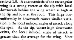
ANA Rectangular wing stall explanation

The ANA's explanation for why a rectangular wing stalls at the root first can be summed up as such: The rectangular wing planform has a strong wingtip vortex, this vortex causes strong downwash locally at the wing tip, and this downwash causes a relatively large induced angle of attack that culminates in the wing tip sections flying at a lower angle of attack than the rest of the wing, even without any washout.

My confusion stems from how extra downwash can be created at the wingtip. Assuming the wing has no washout / twist, the coefficient of lift near the wingtip is lower than near the root, as is shown by the first image. If the lift coefficient is lower at the wingtip, how can the wing tip create more downwash than at the root?

Further contributing to this confusion is This question relating to elliptical wings. Peter's answer begins by stating that circulation (analogous to lift), can be interpreted as local lift coefficient times local chord.

How do these seemingly interfering explanations relate? Is there truly more downwash near the wingtip of a rectangular wing? Why does a rectangular wing have a lower lift coefficient at the tip than near the root? What about the shape of an "elliptical" wing allows a continuous lift coefficient to develop across the entire span?

$\endgroup$
0

2 Answers 2

3
$\begingroup$

The local lift is:

$l=c_l\, c\,q$

The local lift always goes to zero at the wingtip. If the tip chord is non-zero, this means that the local lift coefficient at the tip will be zero. If the tip airfoil had a pressure difference from top to bottom, that pressure would escape around the tip and equalize -- preventing any lift.

An elliptical wing has an elliptical chord distribution and also lift distribution. So while the lift distribution goes to zero at the tip, so does the chord distribution. These go together and an elliptical wing ends up with a constant $c_l$ lift coefficient distribution.

A rectangular wing has a constant chord. But we know the lift must go to zero at the tip. As it turns out, the lift coefficient will start out at a maximum at the root and will gradually fall off to zero at the tip - as shown by curve B from ANA.

The local lift coefficient is a measure of how hard that particular section is working. For an elliptical wing, $c_l$ is constant -- and when the angle of attack is increased, all sections will reach the $c_{l,\mathrm{stall}}$ at the same time -- the whole wing will stall simultaneously.

For our rectangular wing, $c_l$ is greatest at the root, gradually decreasing to the tip. Consequently, as angle of attack is increased, the root will reach $c_{l,\mathrm{stall}}$ first, while the tip is still far from stall.

The local lift can also be written in terms of circulation...

$l=c_l\, c\,q = \rho\,V_\infty\,\gamma$

We can write out the dynamic pressure $q=0.5\,\rho\,{V_\infty}^2$

$c_l\, c\,0.5\,\rho\,{V_\infty}^2 = \rho\,V_\infty\,\gamma$

And then cancel some terms...

$c_l\, c\,0.5\,V_\infty= \gamma$

or

$c_l\, c= \frac{2\,\gamma}{V_\infty}$

This doesn't reveal anything particularly profound -- other than we can work in terms of the local lift distribution $l$, the circulation distribution $\gamma$, or the product of lift coefficient and local chord $c_l\,c$.

In fact, you will also see people work in terms of the last one divided by the average chord.

$\frac{c_l\,c}{\bar{c}}$

Since all of these expressions are equal to the local lift multiplied or divided by some constant or another, they will all have the same shape on a graph -- with the y-axis scaled by the constant.

$\endgroup$
6
  • $\begingroup$ Excellent explanation for both the elliptical and rectangular wing and how they both must naturally achieve zero lift at the wing tip. It sounds like you are saying that the reduction of CL near the tips of the rectangular wing is aerodynamically caused by air pressure "bleeding over" from under the wing to the top of the wing. This sounds like a similar explanation to the excerpt from ANA I posted in the original question. So my secondary question is this: How does this all cause the stall to be delayed near the tips of the rectangular wing? Are the tips not at the same AOA as the root? $\endgroup$ Commented Aug 17, 2023 at 17:49
  • $\begingroup$ Basically, how does this exchange in pressure across the top and bottom of the wing tips cause an increase in stall AOA? Would adding additional pressure to the top of the wing not exacerbate the adverse pressure gradient that causes the stall in the first place? $\endgroup$ Commented Aug 17, 2023 at 17:51
  • $\begingroup$ I don't think anybody said anything about increasing stall AoA. There might be some slight changes, but those get complicated. Lets pretend for a moment that part of the wing will start stalling at 10deg. In one case (rectangular wing) that happens inboard. Since it starts in one place and spreads, it will happen gradually -- the airplane will feel mushy. The tips will remain attached, which means the ailerons will be happy and roll control will be good. $\endgroup$ Commented Aug 17, 2023 at 20:13
  • $\begingroup$ In another case (elliptical), the stall happens across the whole wing at the same time. Stall is more abrupt and has little warning. You lose roll control at the same time. In a third case (strong taper D or E), stall starts at the tip. It is somewhat gradual -- the inboard wing with lots of area keeps lifting. However, you lose roll control. In addition, if you're in a turn, one tip will stall first, causing a strong rolling moment where that wing will 'fall out' from under you. We can understand the implications of lift distribution on handling qualities without a lot of details. $\endgroup$ Commented Aug 17, 2023 at 20:17
  • $\begingroup$ When you talk about a 3D wing, it can be difficult to define the stall AoA. Is it when the first sign of stall happens? Is it when you reach CLmax? The stall curve for a wing can be a sharp point, or it can be a gradual curve. For some wings, it reaches CLmax and pretty much stays there for a long way, not really coming back down. To figure out all the details, you need to get into quite a bit of 3D aerodynamic theory. Start with lifting line theory, move to VLM theory. It is complex and perhaps not worth your time when you can understand the end effect more readily. $\endgroup$ Commented Aug 17, 2023 at 20:21
0
$\begingroup$

Is there truly more downwash near the wingtip of a rectangular wing?

Yes, but let's first clarify terms: Downwash is the downward movement of air added to the flow by the wing when creating lift. The downwash angle is proportional to the product of lift coefficient and chord. In potential flow theory it is proportional to circulation strength. But most important: Downwash occurs only behind the wing.

The flow ahead of the wing experiences upwash. Here, the effect is an induced angle of attack which is proportional to the same factors as downwash is.

Due to the high chord length near the tip, the rectangular wing shows a higher circulation strength near the tip, so downwash is more intense than in more tapered wings. But that is insignificant for your question which concerns stall. See below for more on this.

Why does a rectangular wing have a lower lift coefficient at the tip than near the root?

Tip effects. Since air is free to flow around the wingtip, pressure will equalize there. However, right inside of the wingtip the wing will already have a massive chord, so it will very effectively block this equalization of pressure. This means that the spanwise gradient of circulation is very steep at the wingtip of a rectangular wing. But that rapidly increasing circulation is caused by a lot of chord, so the local lift coefficient starts at zero at the wingtip and only slowly increases towards the root. Note that the rectangular wing has the least "full" lift coefficient distribution over span in the comparison sketch of the ANA.

What about the shape of an "elliptical" wing allows a continuous lift coefficient to develop across the entire span?
Here, chord and circulation move in lockstep over span, so their ratio is always equal. Since the lift coefficient links both, it can stay constant over span.

But what about stall AoA?

Stall is caused by flow separation which in turn is caused by steeper pressure gradients over chord. A positive lift coefficient means that pressure on the upper side of the wing will be lower than on the bottom side. This extra suction must be brought back to ambient pressure at the trailing edge, so a higher lift coefficient needs to be bought with a steeper pressure rise. Since a rectangular wing will have lower lift coefficients near the tip, the local pressure rise over chord is also less steep and flow separation is delayed in comparison with more inbound sections. Stall will happen first at the root.

$\endgroup$
3
  • $\begingroup$ ANA page 66 states that “ One of the important factors in this system is that a downward velocity is created at the aerodynamic center (w) which is one half the final downward velocity imparted to the airstream (2w)”. This goes on further to describe the reduction of CL at the wingtips to be caused by the local downwash increasing the induced AOA, which is what then causes the lower CL at the wingtips. Wingtip vortices adding to local downwash->more overall downwash at the wing tips than at the root->higher induced AOA at the wingtips-> lower section angle of attack-> wing tips stall later. $\endgroup$ Commented Aug 21, 2023 at 19:03
  • $\begingroup$ I’m wondering in the ANA may be either with an outdated understanding of the effects, or may just be written for someone to fly a plane who doesn’t need to understand the intimate engineering facets of why it flies. Its description of the topic doesn’t seem to make sense when it states that there is both more downwash and less overall lift at the tip of the rectangular wing. Your explanation seems to be more intuitive and reasonable. $\endgroup$ Commented Aug 21, 2023 at 19:08
  • $\begingroup$ @EquipmentOperator This view of downwash looks like someone only looked at the vortex and disregarded the translational flow. Then you get the highest up- and downwash at the AC, because that is where the core of the vortex is. In reality, you always have a superposition of rotational and translational flow and in effect the streamlines follow the contour of the wing surface. Which should obviously be correct since air does not enter into nor escape from the wing surface. $\endgroup$ Commented Aug 22, 2023 at 15:52

You must log in to answer this question.

Not the answer you're looking for? Browse other questions tagged .