2
$\begingroup$

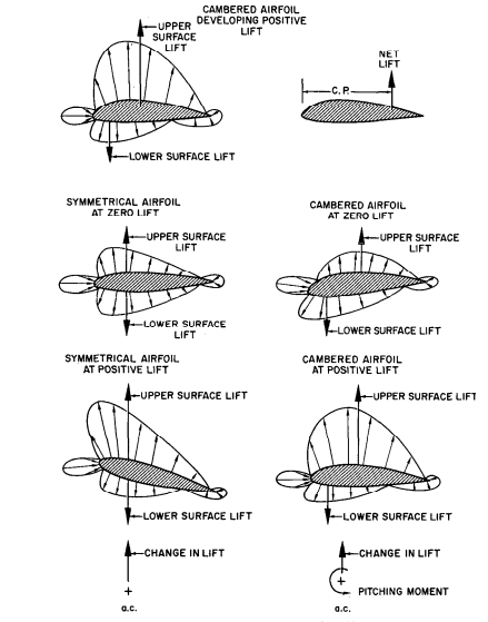
An old flight book that I am reading discusses the aerodynamic moment about a wing and talks about an upper and lower lifts. I can see how the pressure distribution on the top surface produces an upper lift force while the the pressure distribution on the bottom surface produces also a lower lift force. The upper lift force points upward while the lower lift surface points downward. Both lift forces point away from the respective surfaces.

Wouldn't local forces (whose vector sum produces the upper lift force) due to upper pressure distribution point towards the surface, not away, in the normal direction?

As the angle of attack is increased, the upper surface lift increases while the lower surface lift decreases?

It is said that no change in moment takes place about the point where the lift change occurs. I am not sure how to interpret that either... o

$\endgroup$
1
  • $\begingroup$ What is the book? $\endgroup$ Commented Dec 24, 2022 at 9:00

3 Answers 3

1
$\begingroup$

I'm not sure it's very useful to consider the 'upper' and 'lower' lifts in order to determine the moments. It's good and in some cases useful to have a mental picture of pressure distribution above/below the wing, but when talking about integral things like moments, it's better to consider lift as an overall phenomenon for the wing.

The lift theory predicts that the overall centre of pressure will move linearly with the angle of attack (for small (pre-stall) angles, of course). It is this fact that allows us to define a point at which the moment does not change with AoA (and call it Aerodynamic Centre, AC). By doing this, we mentally decompose lift into a 'constant' part at one location and an AoA-dependent part at another (the AC) location. But always remember this is just a mental model; it is not really correct to say that the lift change actually happens at AC.

The phrase "no change in moment takes place about the point where the lift change occurs" as such is a tautology: this is so by definition. The question can only be "how can such a point exist?"

If you dig a bit more into the potential flow theory, you can find a physical explanation of this. Here decomposition of the airfoil (or rather, its lift) in to the 'camber' part and the 'AoA' part is useful. Briefly, the theory says that the centre of pressure (CP) of the camber part is fixed (and determined only by the camber); it is typically close to the middle of the chord. And the CP of the AoA-dependent part is also fixed (at about 1/4 chord), because the picture of its pressure distribution is similar: it just scales up and down. As a result, airfoils behave quite linearly with respect to AoA. But it's not easy to get it just by looking at the picture of the upper and lower pressure distributions as in your pictures.

$\endgroup$
0
$\begingroup$

The lower surface lift vector points downwards in the diagram, not upwards. The nett lift is the sum of the two lift vectors, and since the lower surface lift vector is opposite to the upper, nett lift is upper surface lift minus lower surface lift.

The nett lift points upwards in the top figure, as the upper surface lift is greater than the lower surface lift.

In the middle diagram, both upper and lower surfaces have the same lift magnitude so the nett lift is zero. Note that the chord line of the symmetric airfoil is parallel to the airflow. This wing section has zero angle of attack (angle between the airflow and the chord line), so both the upper and lower surfaces have the same angle of attack and generate the same lift, cancelling each other out. On the cambered airfoil, the angle of attack is slightly negative for zero nett lift. This is because the camber causes the upper surface to generate more lift than the lower surface for a given AoA.

In the lower diagram, the upper surface has an increased angle of attack, while the lower surface has a decreased angle of attack. So the lift of the upper surface is increased and that of the lower surface is decreased, and the nett lift is upward.

Note that the terms "up" and "down" have to be used carefully, since we usually use those terms in the context of gravity. A lift-producing airfoil has no concept of gravity, only of angle of attack. The airfoils in the diagram would produce the same lift with respect to the angle of attack regardless of the orientation of the airfoil with respect to gravity. If you turned any of these diagrams upside down, the airfoils would produce exactly the same lift with respect to the surface as they did in the original ("upright") orientation.
$\endgroup$
0
0
$\begingroup$

May seem strange to talk about the lower part of the wing producing "lift" towards the ground, but this is exactly what its curved surfaces are doing at lower AoA relative to the airflow. Note that if you invert the wing, these forces will remain the same if the AoA does not change! Symmetrical wings are found on many aerobatic aircraft.

The gist of the diagrams is that cambered airfoils start producing lift at a lower AOA than symmetrical airfoils. This information can be readily obtained by looking at polar graphs at Airfoil Tools on the internet, which show lift and drag properties for the entire range of AOA (from stall at negative AOA to stall at positive AOA).

Learning to read polars will be greatly beneficial in evaluating airfoil properties and for comparitive purposes.

As far as where the center of pressure (net lift) of the wing will be for a given AOA, the general rule of thumb is that it will move towards the leading edge as AOA increases. But keep in mind as AoA increases, the horizontal stabilizer will begin to have positive lift as well. So the TOTAL NET LIFT of the aircraft determines where the center of pressure is, not just the wing net lift contribution.

As far as showing the net center of lift moving REARWARDS as the cambered wing moves from negative AOA to zero AOA, well, it is an old book. Use it as a mental exercise to understand net lift. They seem to be saying the center of pressure shifts less with a symmetrical wing as AoA changes. But don't forget the tail!

$\endgroup$
2
  • $\begingroup$ This discussion is for the wing alone to say that the total pitching moment M_O about a specific ref. point O on the chord for a positively cambered wing can be decomposed as M_O = M_camber +M_lift where M_camber is a constant pure aerodynamic moment, solely due to camber and always present regardless of AoA and lift) and M_lift is a moment linearly depending on the lift L. If the reference point O= AC (aerodynamic center), the overall moment M_O=M_AC=M_camber and does not vary with AoA. Assuming the lift force L is applied at CP, I am still not clear why M_lift=0 when O=AC $\endgroup$ Commented Dec 14, 2018 at 14:21
  • $\begingroup$ From a practical point of view, pitching moments are determined by Cpressure and Ggravity. Pitching "moments" would be relative to CG. AC of a wing (and of the whole aircraft) is more useful to determine directional stability when compared to position of CG. Actual pitching moments relative to AOA are best tested in the wind tunnel, and CP shift with AOA should be included in polar data! I'm not quite buying "M camber is a constant pure aerodynamic moment", and as far as I know (in theory) change in AOA around AC does not create a pitching moment. $\endgroup$ Commented Dec 15, 2018 at 0:39

You must log in to answer this question.

Not the answer you're looking for? Browse other questions tagged .