1
$\begingroup$

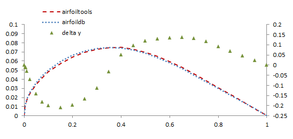
While searching for symmetric profiles I stumbled across different definitions (point-clouds) of the NACA 642-015A profile.

  1. http://airfoiltools.com/airfoil/seligdatfile?airfoil=n64015a-il
  2. http://www.airfoildb.com/airfoils/418.dat

The figure below (skewed) shows the difference in percent chord on the secondary axis (green markers).

enter image description here

What causes these differences and is there a analytical description I could use to create a point-cloud with higher resolution.

Another question is: The NACA Reports I could find via Google all feature the NACA 642-015 (without the "A"). The difference between NACA 642-015A and NACA 642-015 is an increased thickness of the A-version towards the trailing edge. Who introduced or developed the A-version?

$\endgroup$
3
  • $\begingroup$ Have you tried Theory Of Wing Sections by Abbott & Von Doenhoff? $\endgroup$
    – Koyovis
    Commented Jul 31, 2017 at 12:30
  • $\begingroup$ sure, but I could not find the 64_2 015A in them, do you have a profile description in yours? $\endgroup$
    – rul30
    Commented Jul 31, 2017 at 12:41
  • $\begingroup$ The "A" simply denotes that the last 20% of the contour are straight lines. This was made to simplify the construction of wing and flaps. $\endgroup$ Commented Aug 7, 2017 at 11:11

1 Answer 1

1
$\begingroup$

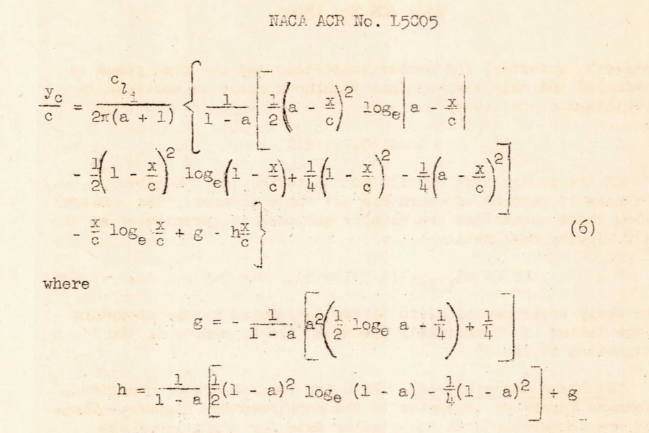
This report seems to include a reference to an analytical description of 6-series airfoils

enter image description here

On your second question: found this reference in Synthesis Of Subsonic Airplane Design by E. Torenbeek:

A modification to the standard series is the A-series in which the sharp trailing edge angle is replaced by a larger one, resulting from straight contours which run from 80% chord backwards.

The paragraph contains a reference to "Theoretical and experimental data for a number of NACA 64-series airfoil sections" which turns out to be NACA LM R6J01

$\endgroup$
2
  • $\begingroup$ Thanks @Koyovis, this helped a lot, really!. BUT (I'll open a new question for this though, I am not able to use the equations to create the airfoils. I'll get there, thanks! $\endgroup$
    – rul30
    Commented Jul 31, 2017 at 15:27
  • 1
    $\begingroup$ Actually I just realised that the equation you cited does not recreate the thickness-distribution but the chamber-line, which is a straight line for a symmetrical airfoil. $\endgroup$
    – rul30
    Commented Aug 1, 2017 at 20:17

You must log in to answer this question.

Not the answer you're looking for? Browse other questions tagged .