8
$\begingroup$

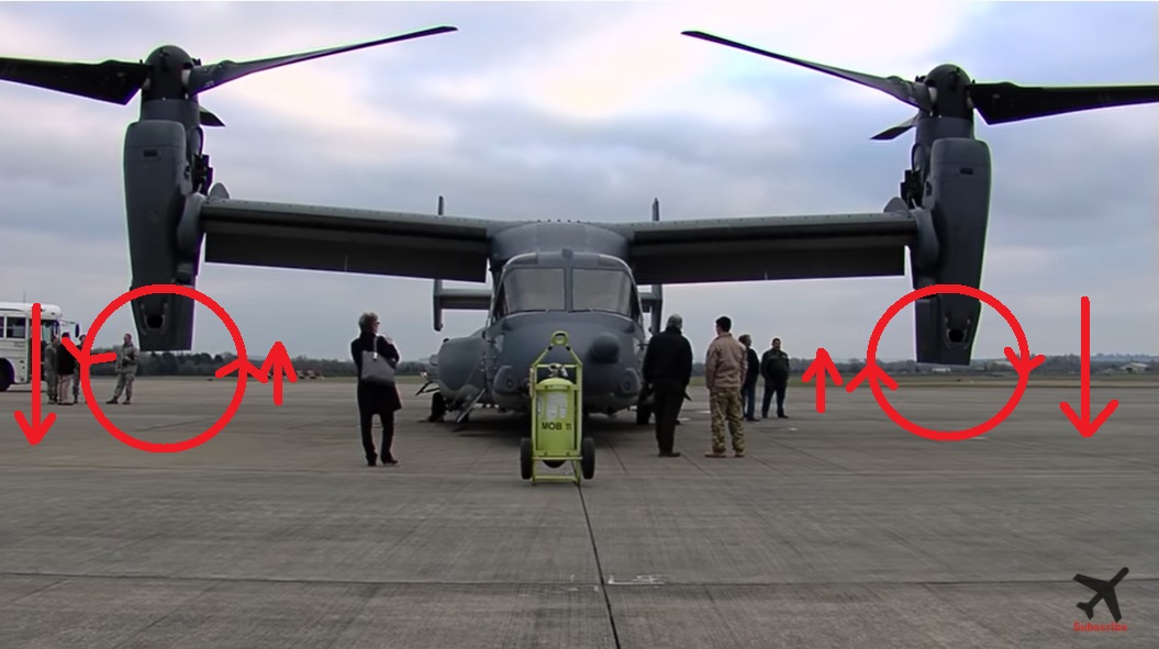
V-22 Osprey's prop-rotor

Picture source:

By seeing the blades, we know the rotation's directions. The right side is clockwise and the left side is anti-clockwise. Both seen from the pilot/rear side. During the cruise, the rotation's direction will be like the red marked circles. With such rotation, the rotors will have P-factors on the outer side of both rotors. Mean, on the outer side the thrust will be bigger than on the inner side near the fuselage as depicted by the red straight line. The longer line indicating the bigger thrust are generated and the shorter line indicating the smaller thrust. Of course all will be fine if all working well. The problem is, if one rotor/propeller get fail then another rotor will create more moment to the center of the Yaw-axis, compared to if the rotors rotate in the opposite direction. By rotate in the opposite direction, the bigger thrusts will be near the fuselage so it will be easier to be handled as the yaw force will be smaller.

Then my question is, why did they design so? Why didn't the P-factor put on the inner side near the fuselage to reduce moment to the yaw-axis if one rotor fails?

$\endgroup$
2
  • $\begingroup$ Comments are not for extended discussion; this conversation has been moved to chat. $\endgroup$
    – Jamiec
    Commented Nov 23, 2022 at 18:57
  • 2
    $\begingroup$ Please check this answer from @mins - upon a single engine failure, both props are still driven by the remaining engine. $\endgroup$
    – Koyovis
    Commented Nov 24, 2022 at 5:32

3 Answers 3

10
$\begingroup$

A couple of things.

One, I suspect the reason is similar to why the arrangement is also used on the P-38 Lightning airplane from World War II. The counterrotating engines on that airplane originally turned in a direction which provided more favorable asymmetric thrust, but during test flying, they found that the propwash interfered with elevator control resulting, I believe, in the death of a test pilot during one flight.

Having a right engine turning clockwise, and a left engine turning counterclockwise, causes the propwash vortices to move out board and avoid interference with the empennage during forward flight.

The second reason on the Osprey is that both engines are interconnected by a drive shaft that runs span wise between the two engine nacelles. This is necessary, not only for forward flight in the event of an engine failure, but also in hover/vertical flight, where an engine failure would be far more disastrous if both drivetrains were not interconnected. I suspect that that transverse driveshaft provides an equivalent level of safety to prevent an accident both in hover and in forward flight.

$\endgroup$
13
  • 1
    $\begingroup$ This is correct, but even more important, I'm pretty sure that in the Osprey, even in horizontal flight, if a rotor fails the aircraft will crash. It certainly can't land with only one rotor. So there is no need to minimize or worry about P-factor in that scenario. $\endgroup$ Commented Nov 23, 2022 at 22:56
  • 2
    $\begingroup$ Is there not also the effect of cancelling out rotational forces, negating the need for a tail rotor? Similar to the Chinook? $\endgroup$
    – SnakeDoc
    Commented Nov 24, 2022 at 1:00
  • 1
    $\begingroup$ @AirCraftLover Search up the flying pancake. High pressure beneath the wing makes it want to spiral up around the tip onto the top of the wing. A tip mounted propeller swirling air the opposite direction alleviates this and increases efficiency. It effectively makes the wing longer. $\endgroup$
    – DKNguyen
    Commented Nov 24, 2022 at 2:30
  • 1
    $\begingroup$ @SnakeDoc You are quite correct. Without a tail rotor or thrust vectoring, the vertical flight regime would be impossible if the rotors did not counter-rotate. $\endgroup$
    – Max R
    Commented Nov 24, 2022 at 4:19
  • 1
    $\begingroup$ Everyone here needs to consider what a "propeller failure" even means. There is also some terminology peculiar to V-22 which is missing here, and which suggests that none of the commenters are actually osprey experts. $\endgroup$
    – fectin
    Commented Nov 24, 2022 at 4:28
4
$\begingroup$

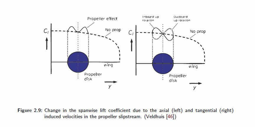
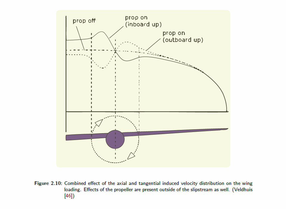
I can't really comment on Carlo's answer about interference with the empennage, but one result of the wingtip propellers turning against the tip vortex is that it effectively increases the length of the wing and aspect ratio, increasing efficiency (in forward flight at least).

One interpretation of this is that it helps reducing the high pressure air under the wing from spilling up and around the edge to the top of the wing. Another is that it reduces the size of the tip vortex. Yet another is that it recaptures the energy in the tip vortex (this is less clear to me though since you have to drive the propeller against the tip vortex which seems like it could mean more work???).

It's not often used because propellers on the wingtips can be structurally difficult, are vulnerable to damage, and this effect works best with very large propellers. But these are things the Osprey already has to live with anyway.

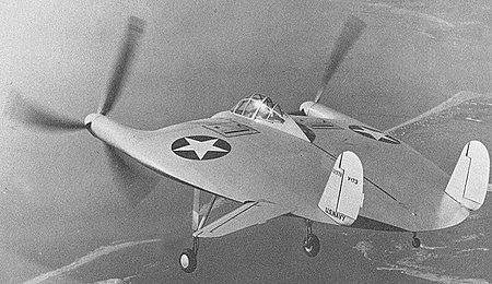
The Flying Pancake took particular advantage of this and my understanding is that it actually relied on the effective increase in aspect ratio to fly (it isn’t going to glide):

Enter image description here

Vought V-173 (Wikipedia)

Enter image description here

Enter image description here

"Experimental and numerical study on wingtip mounted propellers for low aspect ratio UAV design" by Momchil Dimchev

$\endgroup$
2
$\begingroup$

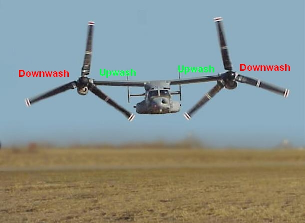
Since the interconnection between motors eliminates the P factor concern, flight efficiency is much better served by inboard up rotation. In horizontal flight the entire wing is placed in the inboard upwash from the ascending propeller blades, getting increased lift essentially free. There is no wing in the outboard downwash as the wing terminates at the engine.

enter image description here

$\endgroup$
4
  • $\begingroup$ After I compared the V-22 to AW609 and to V-280 with all them are different their empennage form (V-22 is double boom, AW609 is single boom T-shape tail, while the V-280 is V-shape empennage), I then came to conclusion that it is the answer. To make the downwash in outer side will create more lift beneath the wing and beneath the tail. The high T-shape tail of AW609 (reducing effect on the empennage) I think gives more confirmation about it. But however, I think no relation to the interconnection rotor. $\endgroup$ Commented Nov 25, 2022 at 4:37
  • $\begingroup$ An aircraft in flight does not need more lift, though it would benefit from less drag. Can this increased angle of attack (compared to a hypothetical mirror image of the V22) be traded for less drag? Well, at a given speed, weight and g-loading, both aircraft will need to produce the same lift, and if the only influence of rotor direction is on the angle of attack, they will produce the required lift at the same angle of attack - but then the drag of the wing will be the same... $\endgroup$
    – sdenham
    Commented Nov 25, 2022 at 16:57
  • $\begingroup$ ... The drag of the rest of the aircraft may differ due to a difference in pitch, but could that not be compensated for by designing a different angle of incidence of the wing and horizontal stabilizer? To be clear, I suspect there is a wing-rotor interaction making the direction of rotation important, but I feel, from the above, that it is more than a change in the angle of attack - maybe a matter of the lift distribution, or in making the transition between hovering and cruising flight? $\endgroup$
    – sdenham
    Commented Nov 25, 2022 at 16:57
  • $\begingroup$ Since propellers increase wing's local AoA during horizontal flight, a loss of power will not stall the wing. $\endgroup$
    – user21228
    Commented Dec 3, 2022 at 16:36

You must log in to answer this question.

Not the answer you're looking for? Browse other questions tagged .