4
$\begingroup$

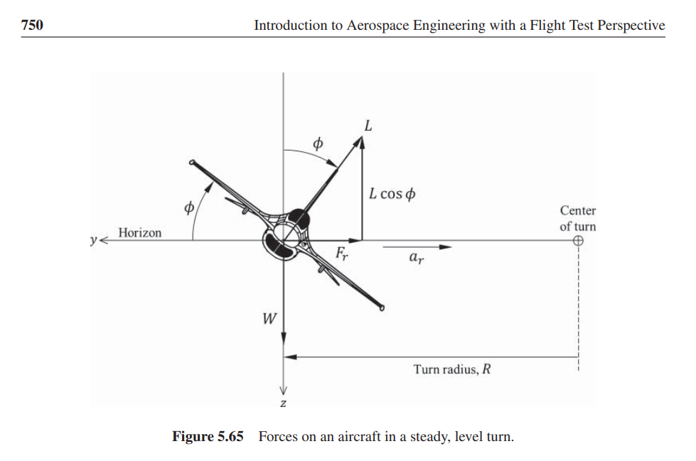
I've been told by someone else that in a stable flight when the vertical path of the aircraft is maintained, the Nz value is equal to cos(pitch)/cos(bank), but I can't seem to figure out how that is derived, the only place on the whole internet where I was able to find that info was here: Inside another stack exchange post, however, it didn't explain how was the formula derived. I do understand that inside a banked turn with 0 disturbance to the vertical path the aircraft's load factor is defined by 1/cos(bank) as explained in the textbook I read: Introduction to Aerospace Engineering with a Flight Test Perspective. enter image description here
But this doesn't explain the cos(pitch) part of the formula, and nowhere was I able to find anything related to it on the internet. Can someone please explain this to me? Thanks!

$\endgroup$
3
  • $\begingroup$ Intuition: load factor in a straight unaccelerated climb is cos(pitch). So in turning unaccelerated flight we simply multiply the load factor for climb and for turning. However I'm not sure how to prove this intuition more rigourously. $\endgroup$
    – Sanchises
    Commented Dec 18, 2020 at 17:54
  • $\begingroup$ @Sanchises "chandelle" $\endgroup$ Commented Dec 18, 2020 at 23:08
  • $\begingroup$ @Robert A chandelle comes with a decrease in airspeed so it's not unaccelerated. $\endgroup$
    – Sanchises
    Commented Dec 24, 2020 at 11:14

2 Answers 2

2
$\begingroup$

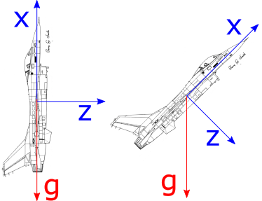
Let's look at the extreme case of a 90° pitch attitude. The airplane climbs vertically. Thankfully, in case of an F-16 without loads this is possible (left side of sketch below).

F-16 with body axis system

The vertical load factor is defined in the body axis system (blue arrows): $n_z$ is the multiple of gravitational acceleration that presses the pilot into his seat. With $\Theta$ = 90° no gravitational acceleration along the body z axis is left (red arrow), all acts along the body x axis. So here $n_z$ is zero and $n_x$ is -1. Gravitational acceleration presses the pilot into his backrest, but his behind is unloaded.

Since the cosine is 1 for 0° and 0 for 90°, it describes the variation in $n_z$ over pitch. For 180° the cosine becomes -1 and the pilot will hang in his shoulder straps. And so on. The right side of the sketch shows an intermediate case and it should be immediately clear that the component of g in z direction is sin(45°) = 1/√2.

Combine this with the change in $n_z$ for a turn and the formulas $$n_x = -\frac{sin\Theta}{cos\phi}$$ $$n_z = \frac{cos\Theta}{cos\phi}$$ should make sense. Since the x axis is defined as positive in flight direction, the x component of the load factor is negative with positive pitch attitude, hence the sign of the equation for $n_x$.

$\endgroup$
5
  • $\begingroup$ Is there a convention that (large) Nz corresponds to an aircraft referenced z axis? (Since large L is). The diagram seems to show "z" as an earth referenced vector. $\endgroup$ Commented Dec 18, 2020 at 22:34
  • $\begingroup$ @RobertDiGiovanni Z is moving with the aircraft - how can it be earth referenced? $\endgroup$ Commented Dec 18, 2020 at 22:38
  • $\begingroup$ The answer would imply a flat earth. Thanks to you and Sanchises, we now have a combined formula for lift requirement plane referenced. I am finding it much easier to decompose the weight vector, and leave the (aircraft generated) lift, thrust, and drag vectors whole. $\endgroup$ Commented Dec 18, 2020 at 23:02
  • $\begingroup$ my friend has confused neutral vpath G load with a V-n diagram G load and thinks that the G load increases with airspeed, can you please so the difference between the two. Also, the answer above is pretty good I just didn't quite get why Nx is = -sin(theta)/cos(phi), anyway thanks for the answer. $\endgroup$ Commented Dec 19, 2020 at 3:32
  • $\begingroup$ @JonathanOrr The possible g load does indeed increase with airspeed, but then you have a nonzero pitch rate which needs to be added to the equations above. $\endgroup$ Commented Dec 19, 2020 at 6:02
0
$\begingroup$

In a stable level turn vertical component "z" will equal the weight of the plane (in order to maintain altitude). Assuming no change in velocity, the AOA must be increased by AOA/cosine bank angle (as long as the plane does not exceed stall AOA).

G load in a turn = 1/cosine bank angle. Increase in coefficient of lift is generally linear to increase in AOA.

A refinement to the reasoning might be to consider the increase in AOA from level flight AOA. For example: if 1/cosine bank angle = 1.5 and my AOA is for level flight is 6 degrees, my AOA in the turn is 9 degrees. If the plane stalls at 12 degrees, this turn is safe.

("AOA level flight" would be the difference of AOA zero lift and AOA required for level flight. Some wings have a negative zero lift AOA).

To summarize mathematically for level flight:

AOA turn/AOA level flight = 1/cosine bank angle

But...

For a stable flight when the vertical path is maintained

This implies a climb, level, or descending flight! Here, for all three cases, lift = weight x cosine pitch (to the horizon).

So, we may include "cosine pitch (to the horizon)" in our lift and turn formula as Nz = cosine pitch/cosine bank angle.

Amazingly, because lift is less than weight in a climb, the stall speed is lower. The F-16 is perfect for this concept, as it has the excess thrust to make it happen.

$\endgroup$
2
  • $\begingroup$ -1 answer does not contain a derivation for the load factor n=cos(pitch)/cos(phi) as per the question. $\endgroup$
    – Sanchises
    Commented Dec 18, 2020 at 17:48
  • $\begingroup$ please see edits $\endgroup$ Commented Dec 18, 2020 at 23:53

You must log in to answer this question.

Not the answer you're looking for? Browse other questions tagged .