11
$\begingroup$

According to the NTSB, the installation of a glideslope serving runway 11 at KHTS (Tri-State Airport, Huntington, West Virginia) was delayed for over twelve years by the lack of suitable terrain for the glideslope antenna, and, when the glideslope was finally installed (following a CFIT accident involving an aircraft making a nighttime approach to runway 11), these same terrain considerations forced the use of a nonstandard installation utilising an offset antenna (my emphasis):

An instrument landing system was scheduled for installation and commissioning at the Tri-State Airport in June 1958. The localizer, middle marker, and outer marker installations were completed at that time, but there was insufficient terrain to provide adequate reflecting surface for the glide-slope antenna, within the existing criteria. Three applications for runway extension, which would also provide suitable terrain for the glide-slope antenna, were submitted to the FAA in Fiscal Years 1967, 1970 and 1971. The 1967 and 1970 requests were not approved because the necessary “matching funds” from the sponsoring agency were not available, and consequently the Federal funds were not committed. The 1971 request was still under consideration at the time of the accident.

Subsequent to the accident, concurrent negotiations involving the FAA, West Virginia State Aeronautics Commission, Wilcox Electric Company, Inc., and the Tri-State Airport Authority, resulted in the installation of a nonstandard glide slope for Runway 11, paid for by Federal funds only. Prior to installation, the FAA estimated that there was a 50 percent probability of success with the glide slope. A Wilcox Mark I, Series 8020 transmitter was placed 1,211 feet south of the runway centerline and 960 feet west of the Runway 29 threshold. The elevation of the site was 805.2 feet m.s.l. and the antenna was rotated 13.5° to align with the middle marker. This offset was required to place the site on suitable terrain, and resulted in an unuseable signal below 1,075 feet m.s.l. Consequently, there was no reduction in the minimum altitude authorized for the instrument approach. However, the signal generating capability of the facility to date has been as reliable as standard systems. [NTSB AAR72-11, page 12 (numbered as 9); the runway has since been extended, and now measures 7,017 feet (and is now runway 12/30, due to changes in the local magnetic declination over time).]

The requirement for “adequate reflecting surface” is surprising; intuitively, one would expect that UHF-radio-wave-reflecting surfaces near your glideslope antenna would be a bad thing, due to the potential for multipath interference from reflected glideslope signals. Why is this not so?

$\endgroup$
3
  • 1
    $\begingroup$ You ask good, well written questions! $\endgroup$
    – FreeMan
    Commented Mar 27, 2020 at 18:00
  • 1
    $\begingroup$ Yeah, by the third paragraph I knew this was a Sean! $\endgroup$ Commented Mar 27, 2020 at 21:23
  • $\begingroup$ @Harper-ReinstateMonica: The third paragraph is me quoting the NTSB... $\endgroup$
    – Vikki
    Commented Mar 28, 2020 at 0:46

2 Answers 2

12
$\begingroup$

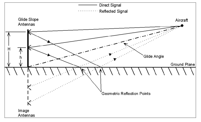
enter image description here
Source: FAA 6750.16E - Siting Criteria for Instrument Landing Systems

The more common G/S antenna type works by reflecting the signal off flat ground, called "image type".

A non-image type was not available in the 70s as it's a mid-90s invention (patent; IEEE).

$\endgroup$
3
  • $\begingroup$ Forgive my ignorance, but aren't the arrows on the solid lines between the aircraft and the antennae the wrong way round? I was under the impression that the antennae transmitted signasl and the aircraft received signals? $\endgroup$ Commented Mar 27, 2020 at 14:01
  • 3
    $\begingroup$ @DaveGremlin: You mean the arrowhead-like shapes drawn on the pole? Those are the two antennas, not signal direction. $\endgroup$
    – user14897
    Commented Mar 27, 2020 at 14:04
  • 3
    $\begingroup$ You're right, I interpreted them as equivalents of the solid black triangle arrows on the antennae-to-ground and ground-to-aircraft lines $\endgroup$ Commented Mar 27, 2020 at 14:06
11
$\begingroup$

You wrote that

intuitively, one would expect that UHF-radio-wave-reflecting surfaces near your glideslope antenna would be a bad thing, due to the potential for multipath interference

However, multipath interference is exacly what we want here. The antenna is mounted a certain height above ground and the aircraft receives both the "line of sight" and "ground bounce" signals. These signals create an interference pattern with maxima and minima at certain elevation angles.

There are two antennas mounted at different heights, so that the interference pattern of one antenna is stronger at 0-3° elevation and the other is stronger at 3-5°. Behavior at higher elevation angles is undefined and there are typically some more maxima and minima with a possibility of "false glideslopes", which is why you always approach the glideslope from below.

$\endgroup$
1
  • 1
    $\begingroup$ Nice answer, but I'd like to add that the false glideslopes are not the only reason to capture it from below. And unfortunately it's not always done, see e.g. the Turkish Airlines flight 1951 crash near Amsterdam. $\endgroup$
    – Emil Bode
    Commented Mar 27, 2020 at 17:42

You must log in to answer this question.

Not the answer you're looking for? Browse other questions tagged .