An ILS/IGS1 glideslope - the part of the system that provides vertical guidance to approaching aircraft and allows it to be used for a precision approach2 - works by transmitting two rapidly-pulsing UHF beams3 back along the approach path, one just above the desired glidepath and one just below it. The beam just above the glidepath pulses on and off at a rate of 90 times every second (90 Hz), while the beam just below the glidepath pulses at a rate of 150 Hz; right at the correct glidepath, the two beams are of equal strength. If the signal received by the aircraft’s glideslope receiver is dominated by the 90-Hz beat, this means that the aircraft is too high, and the pilot (or autopilot, if the aircraft is using autoland) needs to descend more steeply, while, if the signal received pulses more strongly at 150 Hz, the aircraft is too low, and the pilot/autopilot needs to slow their descent; the exact degree to which the signal is dominated by one pulse frequency or the other indicates how far the aircraft is from the glidepath.
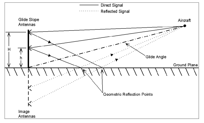
With all glideslope installations, the upper beam is generated about how you would expect; the glideslope transmitter emits a beam of radio energy up and back along the approach path. The process of forming the lower beam, however, is more complicated - the antenna array for this beam is angled downwards, toward the ground, which reflects it back upwards along the approach path:
(Image by the Federal Aviation Administration, via ymb1 here at AvSE.)
This imposes some restrictions on the siting of the glideslope transmitter, as the ground on the approach side of the transmitter has to be suitable for reflecting the lower beam back upwards - this requires a large area of fairly-flat surface in front of the antenna array, which can create problems if, say, the area near the end of the runway is far from flat, potentially making it impossible to install a glideslope or requiring that the transmitter be placed some distance to the side of the approach path (making the glideslope signal unuseable for the final portion of the approach). Even if the terrain is suitable, the requirement for reflecting the lower glideslope beam off the ground creates a fairly-large area in front of the glideslope transmitter where the lower beam is very close to, or even touching, the ground, and anything of significant size and radiointeractivity which enters this area will interfere with the glideslope signal, making this entire area part of the critical area which must be kept free of vehicles and personnel whenever an aircraft is making an approach using the glideslope.
It would seem that a more robust and versatile system could be had if we were to do away with reflecting the lower beam off the ground, and instead simply transmit it up along the approach path in the normal manner, using a second set of antennae mounted lower on the antenna-support structure, or on a separate structure slightly farther back along the approach path; this would eliminate the need to worry about the UHF-reflectivity of the terrain in front of the antennae (since now the proper formation and aiming of neither beam would be dependent on its reflection from said terrain), and greatly shrink the size of the critical area around the antennae (instead of being a great long swath of ground where the lower glideslope beam approaches and meets the ground, it would be a much smaller area in the immediate vicinity of the antennae before the beams rose out of danger), so why does the standard type of glideslope rely on bouncing the lower beam off the ground?
1: An ILS (Instrument Landing System) is when it guides you right down to where you can see the airport out your front windows (visibility permitting); an IGS (Instrument Guidance System) is when it takes you to somewhere near(ish) the airport, but you’ve still got a bunch of manoeuvring to do after that (like that airport they used to have in Hong Kong).
2: Without the glideslope, the system reverts to a bare localiser (ILS) or LDA (IGS), which provides only lateral guidance (the aircraft has to use baroaltimeter or dGPS readings for vertical guidance), and, thus, is only good for a non-precision approach, which has higher minima (to help keep a misset baroaltimeter or GPS receiver from bringing the aircraft in short of the runway).
3: Glideslope transmitters transmit in a narrow range between 326.6 megahertz (MHz) and 335.4 MHz; the precise frequency used varies from glideslope to glideslope (to prevent an aircraft using one glideslope from being confused by signals from a different glideslope nearby), with each specific glideslope frequency being strictly paired with a specific localiser frequency (this allows a pilot to dial in just the localiser frequency - a specific VHF frequency in the 108-112-MHz band - and get the glideslope as well, without having to also manually enter the glideslope frequency). Both the upper and lower beams of a single glideslope installation transmit on the same frequency.

