Short answer
This space is part of the inter-turbine duct (ITD), it is required, as well as the larger LPT stage 1 vanes, to maintain a satisfactory aerodynamic flow between HPT and LPT rotating at different speeds (in the ratio of 1:3) and having different diameters.
Shortened ITD are complex to design and known under the name of aggressive ITD.
Details
Taking the CFM56-7B (Boeing 737 NG) as an example. This engine has a single stage HPT and a 4 stage LPT.
Each rotor is preceded by stator (nozzle). The role of the stator vanes is to convert pressure into velocity and turn the flow more perpendicular to the rotor blades surface (this is opposite to the compressor stages where the vanes are downstream of the blades to convert added velocity into pressure and straighten the flow).
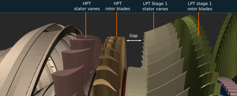
There is a larger space ahead of the LPT stage 1 vanes.
Small gap and larger vanes
Everything is globally continuous, though there is a small gap forward of the LPT stage 1 nozzle which is located in the HPT casing. The vanes themselves are larger axially.

CFM56-7B, small gap before LPT Stage 1 vanes
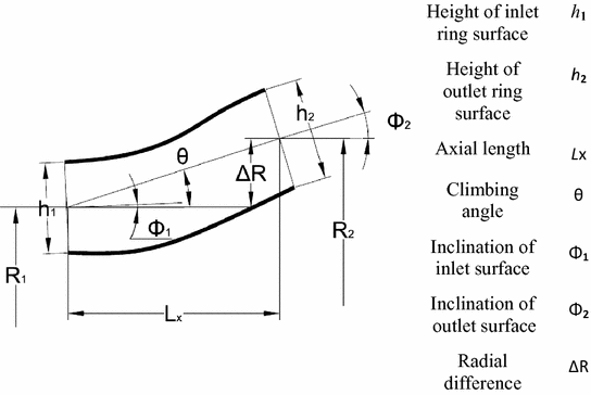
This location is called the inter-turbine (transition) duct, it corresponds to the interface between HPT and LPT which are rotating at different speeds. The duct has an increasing area due to its "S" shape.

Inter-turbine duct geometry. Source
The gap allows to get a smother change and the adequate duct aspect ratio. The longer duct prevents significant pressure loss before reaching the LPT.
To increase engine performance, manufacturers are trying to decrease the length of the duct but this is difficult due to aerodynamic reasons. Shorter ducts are known as aggressive inter-turbine ducts (AITD). See this paper. A similar duct exists between LPC and HPC.
Bearings
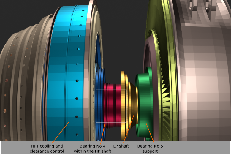
Regarding the possible problem with a bearing or a bearing support in the way, the bearings are really smaller than the stages:

CFM56-7B, location of rear bearings
- The No 4 bearing is within the HP shaft.
- The No 5 outer support is within the oil collector shown above, and the bearing itself is within the its support.
