"What produces Thrust along the line of flight in a glider?" Nothing. There is no Thrust involved in gliding flight. Lift, Drag, and Weight form a closed vector triangle, meaning net force is zero, meaning no acceleration or deceleration is taking place. The Weight vector can be resolved into components perpendicular and parallel to the Drag vector, but noting that Weight has a component that is parallel to Drag is not the same as saying that a Thrust force exists.
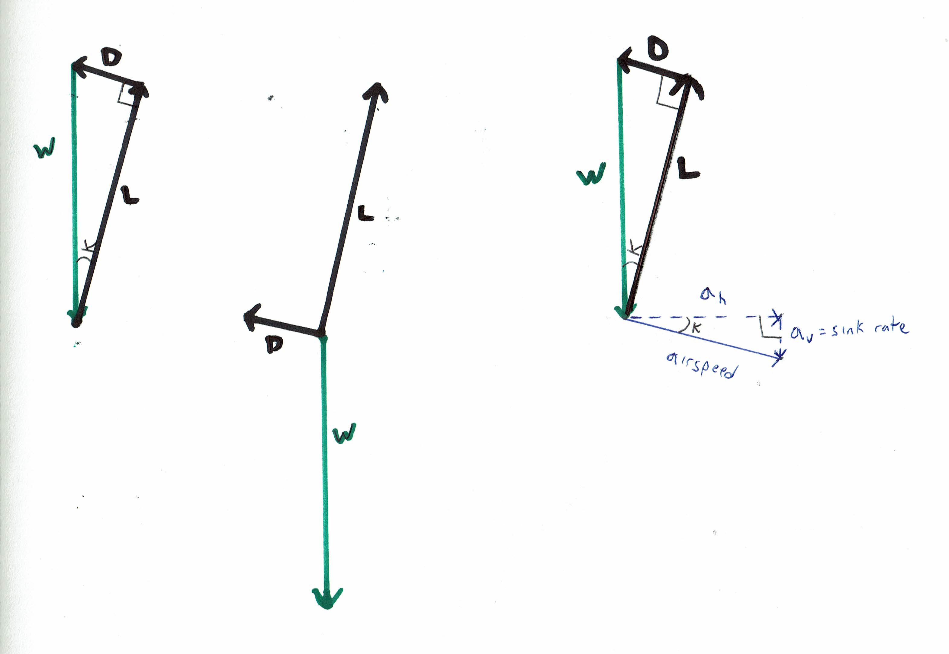
See these vector diagrams:
The balance of forces in gliding flight can be represented by a closed vector triangle of Lift, Drag, and Weight, with right angle between the Lift and Drag vectors. If we wish, we can also show the airspeed vector, and we can break it down into its horizontal and vertical components. The vertical component of the airspeed vector is simply the sink rate.
All three of the above vector diagrams represent the exact same physical situation. We've represented the aerodynamic forces in black, and the gravitational force-- the weight vector-- in green. The left-hand and right-hand diagrams are easier to understand than the middle diagram, because the force vectors are arranged into a closed polygon (a triangle in this case), which shows us instantly that the net force is zero. On the right-hand diagram, we've also included the airspeed vector, and it's horizontal and vertical components. Note that K is the glide angle, and note that on the right-hand diagram, the triangle formed by the force vectors and the triangle formed by the airspeed vectors are similar triangles. The right-hand diagram makes it immediately obvious why the ratio of Lift to Drag, is also equal to the glide ratio through still air-- i.e.the ratio of horizontal speed to vertical speed (sink rate). Note that for high L/D ratios, Lift is very nearly as large as Weight, and horizontal speed is very nearly as large as airspeed, so for most practical purposes we can use airspeed / sink rate, glide ratio, and L/D interchangeably.
The lift vector is proportional to the lift coefficient times the airspeed squared. The drag vector is proportional to the drag coefficient times the airspeed squared. The ratio between the magnitude of the Lift and Drag vectors is identical to the ratio between the lift and drag coefficients. For a given fixed aircraft shape, a change in the lift coefficient and/ or drag coefficient represents a change in angle-of-attack. Every possible angle-of-attack of the wing is associated with a specific lift coefficient, a specific drag coefficient, and a specific Lift : Drag ratio. This is true regardless of whether the aircraft is heavy or light-- a change in weight is expressed as a change in the airspeed associated with any given angle-of-attack, but no change in the lift coefficient, drag coefficient, or Lift: Drag ratio associated with any given angle-of-attack.
It is crucial to understand that the above vector diagrams will be valid for flight at some given particular angle-of-attack of the wing REGARDLESS of whether the airmass is rising, sinking, or neither. A glider doesn't feel any difference in the direction and magnitude of the forces acting on it when rising in a powerful mountain wave, than when gliding in still air.
Note also that we're only dealing with the wings-level case. In circling flight, the forces still look the same in a side view, but airspeed and lift and drag are all higher than in wings-level flight at the same angle-of-attack, and the glide ratio is decreased, and from a head-on view we'd see that the part of the lift vector has been diverted to the side.
Back to the simple case of wings-level flight--
What is "powering" the glider?
Work is proportional to force times distance, and power is proportional to force times velocity. In the airmass reference frame, the glider's direction of travel is identical to the direction the airspeed vector is pointing. The only force doing work on the aircraft in this direction is the component of the weight vector that points in the same direction as the airspeed vector. We can break the Weight vector down into one component that is equal and opposite to the Lift vector, and one component that is equal and opposite to the Drag vector. The latter component is what is "powering" the glider, at least as viewed from the standpoint of the airmass reference frame. The latter component of the Weight vector will be equal to Weight * cosine (glide angle). So the Power exerted by this component of the Weight vector is equal to (Weight * cosine (glide angle)) * airspeed). Now, it just so happens that the sink rate is equal to (airspeed * cosine (glide angle)). So we can say that the power exerted by gravity = (Weight * cosine (glide angle)) * airspeed) = (Weight * (cosine (glide angle)) * airspeed) = Weight * sink rate.
As viewed from the ground reference frame, the glider's direction of travel is different when the glider is in rising airmass than when the glider is in still air, so the above formulae for work and energy will only be valid in still air. From the ground reference frame, the glider's direction of travel is sometimes horizontal or climbing, in which cases the Lift vector can be viewed as having a component that is doing work on the glider. But as noted earlier, the direction and magnitude of the Lift, Drag, and Weight vectors remains the same regardless of what reference frame we are using for our velocity vectors.

