added 505 characters in body
Source Link
sophit
  • 15.8k
  • 1
  • 34
  • 78

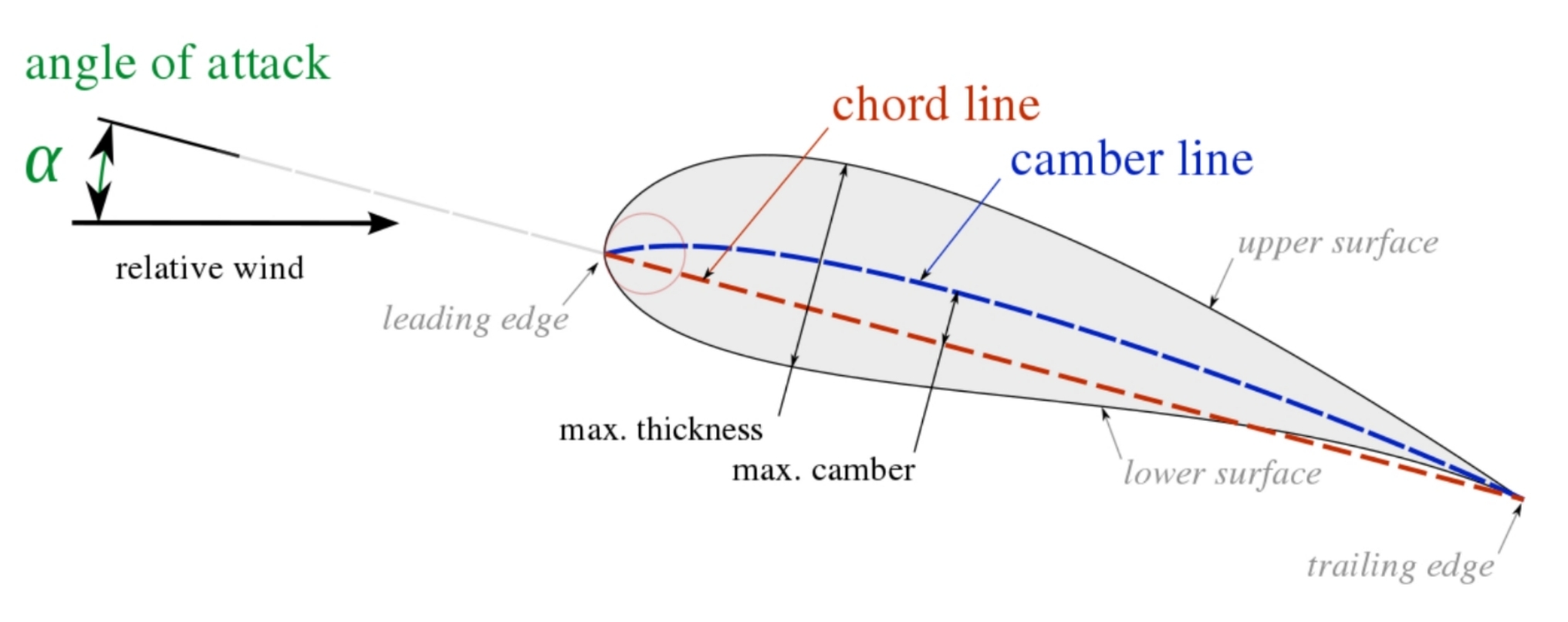
Back to the roots. An airfoil can be basically described by 3 parameters:

  • the shape/curvature of its camber line;
  • the radius of its leading edge (the trailing edge is almost always pointy);
  • the distribution of the thickness upon the camber line.

Those 3 parameters are enough to define any airfoil of practical use (source Wikipedia):

 Airfoil nomenclature

Without any claim to thoroughness (that would cover an entire book) the following can be said:

  • a rounder leading edge and higher thickness give a smooth stall with a progressive loss of lift; pitching moment also changes smoothly approaching the stall region; thick airfoils have also a big volume that can be used for fuel and structure $\rightarrow$ good for the root of a jetliner's wing or of a propeller.
  • a thinner leading edge and thickness give a more nervous stall with a higher pitching moment variation; anyway at high subsonic speeds a thinner airfoil possesses a lower drag than a thick one since it retards the formation of shock waves (which give rise to the boundary layer's detachment and stall) $\rightarrow$ due to structural and aerodynamical reasons, lift on a jetliner's wing and on a propeller should diminish toward the tip: twisting the wing/propeller so that the AoA at its tip is lower than that at the root allows the use of these thinner airfoils with a benefit in terms of drag reduction.
  • a pointy leading edge is necessary at supersonic speeds in order to avoid the formation of a detached (aka bow) shock which increases drag and temperature $\rightarrow$ virtually all the wings of supersonic fighters are built around a very thin, pointy airfoil; the loss in internal volume for fuel and structure is compensated for by the use of delta planform for the wing.
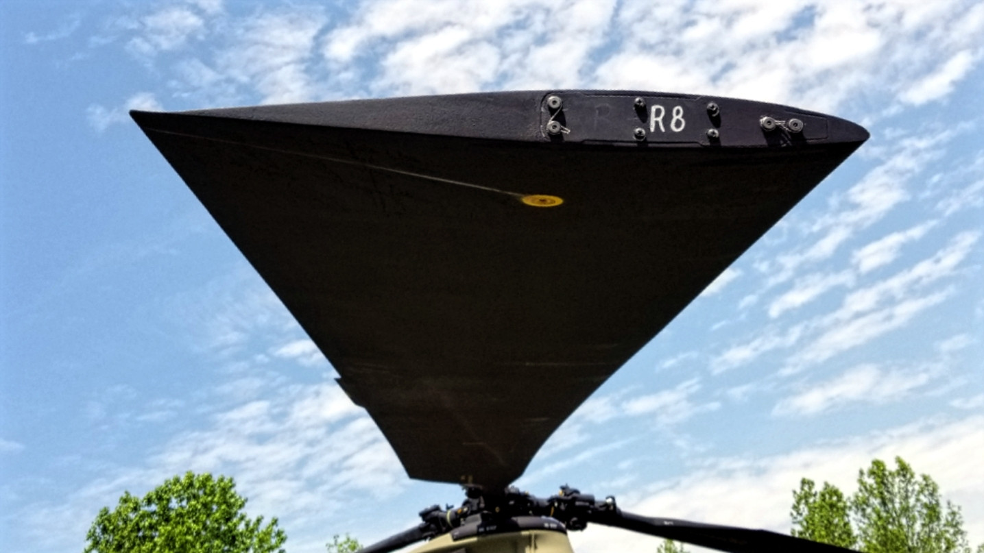
  • camber is mainly used to control/delay stall and limit pitching moment; a very pronounced camber (one that makes the airfoil look like an arc) is used when lift needs to be generated at very high AoA i.e. low speeds; this is typically the shape that a bird's wing possesses or that a jetliner's wing assumes when its high-lift devices are deployed; in those cases a round, thick leading edge helps too, as already said; anyway a lot of camber doesn't work at high speeds since the boundary layer tends to detach and make the airfoil stall; the only exception where high camber and high speed work together is within an axial compressor/turbine: here the adjacent blades "channel" the airflow and make it stay attached also at the high speeds seen by the blades; asblades. As a side effect, an airfoil with high camber generates also a high pitching moment which needs a lot of structure to be carried: also for this reason the turbine blade is quite tick. Totick; to partially offset this, the camber can be built in such a way to go upward toward the trailing edge: so the first, say, ¾ of the chord is arched like the turbofan blade in your picture while the last ¼ is arched the other way around, in a sort of "S" shaped pattern; in this way the good aerodynamic characteristics at high AoA are retained but without the increased torsional moment $\rightarrow$ this is normally seen in helicopter blades (CH-47, source) enter image description here
To get to your original question:

Is the ideal airfoil concave on the underside?

A highly cambered airfoil (such that also the belly is arched) works only when lift is needed at high AoA and low speeds and the high torsional (aka pitching) moment doesn't play an important role. For airfoils in cascade (like in an axial compressor/turbine) the limitation on the speed can be dropped due to the channeling effect. For all the other cases a more subtle camber or even an S-shaped camber is needed.

Back to the roots. An airfoil can be basically described by 3 parameters:

  • the shape/curvature of its camber line;
  • the radius of its leading edge (the trailing edge is almost always pointy);
  • the distribution of the thickness upon the camber line.

Those 3 parameters are enough to define any airfoil of practical use (source Wikipedia):

 Airfoil nomenclature

Without any claim to thoroughness (that would cover an entire book) the following can be said:

  • a rounder leading edge and higher thickness give a smooth stall with a progressive loss of lift; pitching moment also changes smoothly approaching the stall region; thick airfoils have also a big volume that can be used for fuel and structure $\rightarrow$ good for the root of a jetliner's wing or of a propeller.
  • a thinner leading edge and thickness give a more nervous stall with a higher pitching moment variation; anyway at high subsonic speeds a thinner airfoil possesses a lower drag than a thick one since it retards the formation of shock waves (which give rise to the boundary layer's detachment and stall) $\rightarrow$ due to structural and aerodynamical reasons, lift on a jetliner's wing and on a propeller should diminish toward the tip: twisting the wing/propeller so that the AoA at its tip is lower than that at the root allows the use of these thinner airfoils with a benefit in terms of drag reduction.
  • a pointy leading edge is necessary at supersonic speeds in order to avoid the formation of a detached (aka bow) shock which increases drag and temperature $\rightarrow$ virtually all the wings of supersonic fighters are built around a very thin, pointy airfoil; the loss in internal volume for fuel and structure is compensated for by the use of delta planform for the wing.
  • camber is mainly used to control/delay stall and limit pitching moment; a very pronounced camber (one that makes the airfoil look like an arc) is used when lift needs to be generated at very high AoA i.e. low speeds; this is typically the shape that a bird's wing possesses or that a jetliner's wing assumes when its high-lift devices are deployed; in those cases a round, thick leading edge helps too, as already said; anyway a lot of camber doesn't work at high speeds since the boundary layer tends to detach and make the airfoil stall; the only exception where high camber and high speed work together is within an axial compressor/turbine: here the adjacent blades "channel" the airflow and make it stay attached also at the high speeds seen by the blades; as a side effect, an airfoil with high camber generates also a high pitching moment which needs a lot of structure to be carried: also for this reason the turbine blade is quite tick. To partially offset this, the camber can be built in such a way to go upward toward the trailing edge: so the first, say, ¾ of the chord is arched like the turbofan blade in your picture while the last ¼ is arched the other way around, in a sort of "S" shaped pattern; in this way the good aerodynamic characteristics at high AoA are retained but without the increased torsional moment $\rightarrow$ this is normally seen in helicopter blades (CH-47, source) enter image description here

Back to the roots. An airfoil can be basically described by 3 parameters:

  • the shape/curvature of its camber line;
  • the radius of its leading edge (the trailing edge is almost always pointy);
  • the distribution of the thickness upon the camber line.

Those 3 parameters are enough to define any airfoil of practical use (source Wikipedia):

 Airfoil nomenclature

Without any claim to thoroughness (that would cover an entire book) the following can be said:

  • a rounder leading edge and higher thickness give a smooth stall with a progressive loss of lift; pitching moment also changes smoothly approaching the stall region; thick airfoils have also a big volume that can be used for fuel and structure $\rightarrow$ good for the root of a jetliner's wing or of a propeller.
  • a thinner leading edge and thickness give a more nervous stall with a higher pitching moment variation; anyway at high subsonic speeds a thinner airfoil possesses a lower drag than a thick one since it retards the formation of shock waves (which give rise to the boundary layer's detachment and stall) $\rightarrow$ due to structural and aerodynamical reasons, lift on a jetliner's wing and on a propeller should diminish toward the tip: twisting the wing/propeller so that the AoA at its tip is lower than that at the root allows the use of these thinner airfoils with a benefit in terms of drag reduction.
  • a pointy leading edge is necessary at supersonic speeds in order to avoid the formation of a detached (aka bow) shock which increases drag and temperature $\rightarrow$ virtually all the wings of supersonic fighters are built around a very thin, pointy airfoil; the loss in internal volume for fuel and structure is compensated for by the use of delta planform for the wing.
  • camber is mainly used to control/delay stall and limit pitching moment; a very pronounced camber (one that makes the airfoil look like an arc) is used when lift needs to be generated at very high AoA i.e. low speeds; this is typically the shape that a bird's wing possesses or that a jetliner's wing assumes when its high-lift devices are deployed; in those cases a round, thick leading edge helps too, as already said; anyway a lot of camber doesn't work at high speeds since the boundary layer tends to detach and make the airfoil stall; the only exception where high camber and high speed work together is within an axial compressor/turbine: here the adjacent blades "channel" the airflow and make it stay attached also at the high speeds seen by the blades. As a side effect, an airfoil with high camber generates also a high pitching moment which needs a lot of structure to be carried: also for this reason the turbine blade is quite tick; to partially offset this, the camber can be built in such a way to go upward toward the trailing edge: so the first, say, ¾ of the chord is arched like the turbofan blade in your picture while the last ¼ is arched the other way around, in a sort of "S" shaped pattern; in this way the good aerodynamic characteristics at high AoA are retained but without the increased torsional moment $\rightarrow$ this is normally seen in helicopter blades (CH-47, source) enter image description here

To get to your original question:

Is the ideal airfoil concave on the underside?

A highly cambered airfoil (such that also the belly is arched) works only when lift is needed at high AoA and low speeds and the high torsional (aka pitching) moment doesn't play an important role. For airfoils in cascade (like in an axial compressor/turbine) the limitation on the speed can be dropped due to the channeling effect. For all the other cases a more subtle camber or even an S-shaped camber is needed.

added 155 characters in body
Source Link
sophit
  • 15.8k
  • 1
  • 34
  • 78

Back to the roots. An airfoil can be basically described by 3 parameters:

  • the shape/curvature of its chord aka camber line;
  • the radius of its leading edge (the trailing edge is almost always pointy);
  • the distribution of the thickness upon the camber line.

Those 3 parameters are enough to define any airfoil of practical use (source Wikipedia):

 Airfoil nomenclature

Without any claim to thoroughness (that would cover an entire book) the following can be said:

  • a rounder leading edge and higher thickness give a smooth stall with a progressive loss of lift; pitching moment also changes smoothly approaching the stall region; thick airfoils have also a big volume that can be used for fuel and structure $\rightarrow$ good for the root of a jetliner's wing or of a propeller.
  • a thinner leading edge and thickness give a more nervous stall with a higher pitching moment variation; anyway at high subsonic speeds a thinner airfoil possesses a lower drag than a thick airfoilone since it retards the formation of shock waves (which give rise to the boundary layer's detachment and stall) $\rightarrow$ twisting the wing ofdue to structural and aerodynamical reasons, lift on a jetliner or ofjetliner's wing and on a propeller should diminish toward the tip: twisting the wing/propeller so that the AoA at its tip is lower than that at the root allows the use of these thinner airfoils with a benefit in terms of drag reduction.
  • a pointy leading edge is necessary at supersonic speeds in order to avoid the formation of a detached (aka bow) shock which increases drag and temperature $\rightarrow$ virtually all the wings of supersonic fighters are built around a very thin, pointy airfoil; the loss in internal volume for fuel and structure is compensated for by the use of delta planform for the wing.
  • camber is mainly used to control/delay stall and limit pitching moment; a very pronounced camber (one that makes the airfoil look like an arc) is used when lift needs to be generated at very high AoA i.e. low speeds; this is typically the shape that a bird's wing possesses or that a jetliner's wing assumes when its high-lift devices are deployed; in thisthose cases a round, thick leading edge also helps too, as already said; anyway a lot of camber doesn't work at high speeds since the boundary layer tends to detach and make the airfoil stall; the only exception where high camber and high speed work together is within an axial compressor/turbine: here the adjacent blades "channel" the airflow and make it stay attached also at the high speeds seen by the blades; as a side effect, an airfoil with high camber generates also a high pitching moment which needs a lot of structure to be carried; tocarried: also for this reason the turbine blade is quite tick. To partially offset itthis, the camber can be built in such a way to go upward toward the trailing edge: so the first, say, ¾ of the chord is arched like the turbofan blade in your picture while the last ¼ is arched the other way around, in a sort of "S" shaped pattern; in this way the good aerodynamic characteristics at high AoA are retained but without the increased torsional moment: $\rightarrow$ this is normally seen in helicopter blades (CH-47, source) enter image description here

Back to the roots. An airfoil can be basically described by 3 parameters:

  • the shape/curvature of its chord aka camber line;
  • the radius of its leading edge (the trailing edge is almost always pointy);
  • the distribution of the thickness upon the camber line.

Those 3 parameters are enough to define any airfoil of practical use (source Wikipedia):

 Airfoil nomenclature

Without any claim to thoroughness (that would cover an entire book) the following can be said:

  • a rounder leading edge and higher thickness give a smooth stall with a progressive loss of lift; pitching moment also changes smoothly approaching the stall region; thick airfoils have also a big volume that can be used for fuel and structure $\rightarrow$ good for the root of a jetliner's wing or of a propeller.
  • a thinner leading edge and thickness give a more nervous stall with a higher pitching moment variation; anyway at high subsonic speeds a thinner airfoil possesses a lower drag than a thick airfoil since it retards the formation of shock waves (which give rise to the boundary layer's detachment and stall) $\rightarrow$ twisting the wing of a jetliner or of a propeller so that the AoA at its tip is lower than that at the root allows the use of these thinner airfoils with a benefit in terms of drag reduction.
  • a pointy leading edge is necessary at supersonic speeds in order to avoid the formation of a detached (aka bow) shock which increases drag and temperature $\rightarrow$ virtually all the wings of supersonic fighters are built around a very thin, pointy airfoil; the loss in internal volume for fuel and structure is compensated for by the use of delta planform for the wing.
  • camber is mainly used to control/delay stall and limit pitching moment; a very pronounced camber (one that makes the airfoil look like an arc) is used when lift needs to be generated at very high AoA i.e. low speeds; this is typically the shape that a bird's wing possesses or that a jetliner's wing assumes when its high-lift devices are deployed; in this cases a round, thick leading edge also helps, as already said; anyway a lot of camber doesn't work at high speeds since the boundary layer tends to detach and make the airfoil stall; the only exception where high camber and high speed work together is within an axial compressor/turbine: here the adjacent blades "channel" the airflow and make it stay attached also at the high speeds seen by the blades; as a side effect, an airfoil with high camber generates also a high pitching moment which needs a lot of structure to be carried; to partially offset it, the camber can be built in such a way to go upward toward the trailing edge: so the first, say, ¾ of the chord is arched like the turbofan blade in your picture while the last ¼ is arched the other way around, in a sort of "S" shaped pattern; in this way the good aerodynamic characteristics at high AoA are retained but without the increased torsional moment: this is normally seen in helicopter blades (CH-47, source) enter image description here

Back to the roots. An airfoil can be basically described by 3 parameters:

  • the shape/curvature of its camber line;
  • the radius of its leading edge (the trailing edge is almost always pointy);
  • the distribution of the thickness upon the camber line.

Those 3 parameters are enough to define any airfoil of practical use (source Wikipedia):

 Airfoil nomenclature

Without any claim to thoroughness (that would cover an entire book) the following can be said:

  • a rounder leading edge and higher thickness give a smooth stall with a progressive loss of lift; pitching moment also changes smoothly approaching the stall region; thick airfoils have also a big volume that can be used for fuel and structure $\rightarrow$ good for the root of a jetliner's wing or of a propeller.
  • a thinner leading edge and thickness give a more nervous stall with a higher pitching moment variation; anyway at high subsonic speeds a thinner airfoil possesses a lower drag than a thick one since it retards the formation of shock waves (which give rise to the boundary layer's detachment and stall) $\rightarrow$ due to structural and aerodynamical reasons, lift on a jetliner's wing and on a propeller should diminish toward the tip: twisting the wing/propeller so that the AoA at its tip is lower than that at the root allows the use of these thinner airfoils with a benefit in terms of drag reduction.
  • a pointy leading edge is necessary at supersonic speeds in order to avoid the formation of a detached (aka bow) shock which increases drag and temperature $\rightarrow$ virtually all the wings of supersonic fighters are built around a very thin, pointy airfoil; the loss in internal volume for fuel and structure is compensated for by the use of delta planform for the wing.
  • camber is mainly used to control/delay stall and limit pitching moment; a very pronounced camber (one that makes the airfoil look like an arc) is used when lift needs to be generated at very high AoA i.e. low speeds; this is typically the shape that a bird's wing possesses or that a jetliner's wing assumes when its high-lift devices are deployed; in those cases a round, thick leading edge helps too, as already said; anyway a lot of camber doesn't work at high speeds since the boundary layer tends to detach and make the airfoil stall; the only exception where high camber and high speed work together is within an axial compressor/turbine: here the adjacent blades "channel" the airflow and make it stay attached also at the high speeds seen by the blades; as a side effect, an airfoil with high camber generates also a high pitching moment which needs a lot of structure to be carried: also for this reason the turbine blade is quite tick. To partially offset this, the camber can be built in such a way to go upward toward the trailing edge: so the first, say, ¾ of the chord is arched like the turbofan blade in your picture while the last ¼ is arched the other way around, in a sort of "S" shaped pattern; in this way the good aerodynamic characteristics at high AoA are retained but without the increased torsional moment $\rightarrow$ this is normally seen in helicopter blades (CH-47, source) enter image description here
Source Link
sophit
  • 15.8k
  • 1
  • 34
  • 78

Back to the roots. An airfoil can be basically described by 3 parameters:

  • the shape/curvature of its chord aka camber line;
  • the radius of its leading edge (the trailing edge is almost always pointy);
  • the distribution of the thickness upon the camber line.

Those 3 parameters are enough to define any airfoil of practical use (source Wikipedia):

 Airfoil nomenclature

Without any claim to thoroughness (that would cover an entire book) the following can be said:

  • a rounder leading edge and higher thickness give a smooth stall with a progressive loss of lift; pitching moment also changes smoothly approaching the stall region; thick airfoils have also a big volume that can be used for fuel and structure $\rightarrow$ good for the root of a jetliner's wing or of a propeller.
  • a thinner leading edge and thickness give a more nervous stall with a higher pitching moment variation; anyway at high subsonic speeds a thinner airfoil possesses a lower drag than a thick airfoil since it retards the formation of shock waves (which give rise to the boundary layer's detachment and stall) $\rightarrow$ twisting the wing of a jetliner or of a propeller so that the AoA at its tip is lower than that at the root allows the use of these thinner airfoils with a benefit in terms of drag reduction.
  • a pointy leading edge is necessary at supersonic speeds in order to avoid the formation of a detached (aka bow) shock which increases drag and temperature $\rightarrow$ virtually all the wings of supersonic fighters are built around a very thin, pointy airfoil; the loss in internal volume for fuel and structure is compensated for by the use of delta planform for the wing.
  • camber is mainly used to control/delay stall and limit pitching moment; a very pronounced camber (one that makes the airfoil look like an arc) is used when lift needs to be generated at very high AoA i.e. low speeds; this is typically the shape that a bird's wing possesses or that a jetliner's wing assumes when its high-lift devices are deployed; in this cases a round, thick leading edge also helps, as already said; anyway a lot of camber doesn't work at high speeds since the boundary layer tends to detach and make the airfoil stall; the only exception where high camber and high speed work together is within an axial compressor/turbine: here the adjacent blades "channel" the airflow and make it stay attached also at the high speeds seen by the blades; as a side effect, an airfoil with high camber generates also a high pitching moment which needs a lot of structure to be carried; to partially offset it, the camber can be built in such a way to go upward toward the trailing edge: so the first, say, ¾ of the chord is arched like the turbofan blade in your picture while the last ¼ is arched the other way around, in a sort of "S" shaped pattern; in this way the good aerodynamic characteristics at high AoA are retained but without the increased torsional moment: this is normally seen in helicopter blades (CH-47, source) enter image description here