9
$\begingroup$

I am currently working on the modeling of blade/casing interactions in aircraft engines. The work is carried out in partnership with a company, therefore, there is a limited amount of it that could be published openly.

Are there any OpenSource compressor or turbine blade designs available (e.g. NACA airfoil profiles for wings)? Where could I find detailed dimensions and material properties?

The idea would be to use it for publication purposes, thus displaying relevant characteristics and realistic behaviors, while keeping all the confidential data of the company internally.

$\endgroup$

4 Answers 4

7
$\begingroup$

Since nobody's answered this yet, I'll take a stab at it.

I tried to find some dimensions for you online, but struggled.

Here's a thought though, could you just buy one?

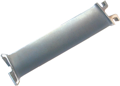
For example - £35:

This is a Rolls Royce Olympus 593 Turbojet engine High Pressure Compressor Vane. This is a flown item that powered BAs Concorde fleet and the blade shows signs of use.

It was manufactured by Rolls Royce and has the Olympus 593 part number B430542.

The dimensions of this item in centimetres are approximately 15.5 x 4 x 4 and it weighs approximately 400g.

There are lots more on eBay too.

You asked about material — one listing says the Tornado's Rolls Royce RB199 engine is made from titanium.

$\endgroup$
5
  • 1
    $\begingroup$ seems like a reasonable solution if used blades are available at such (relatively) reasonable prices. You would have to go over them with a micrometer to get the dimensions (which could be a little time-consuming if the airfoil shape is complex), but it seems do-able. $\endgroup$
    – voretaq7
    Commented Mar 21, 2014 at 22:01
  • $\begingroup$ @DannyBeckett Actually, this is a pretty good idea. Even if for super small compressor blades the measurement procedure would be particularly hard, specially for complex airfoil shapes (as suggested by @voretaq7). I was wondering, if these blades are on the market, do they fall under the public domain ? Can the data then be used freely for publication purposes ? $\endgroup$
    – Nicolas
    Commented Mar 24, 2014 at 19:15
  • 4
    $\begingroup$ @Nicolas That would be a question for your attorney - you shouldn't ask for (or trust) legal advice from an aviation site :-) $\endgroup$
    – voretaq7
    Commented Mar 24, 2014 at 19:23
  • $\begingroup$ @voretaq7 Fair enough ! :-) $\endgroup$
    – Nicolas
    Commented Mar 24, 2014 at 21:53
  • 3
    $\begingroup$ 3D scanning is becoming much easier/cheaper, so put that micrometer away. I would be surprised if RR would allow you to publish that data or use it for profit though. $\endgroup$ Commented Mar 11, 2015 at 15:58
3
$\begingroup$

I was the manufacturing manager at Walbar Canada in Mississauga Ontario. We made all 17 stages of compressor blades and vanes for the RB 199 engine. the information you are looking for is proprietary. The parts were made from 6.2 and 6.2.4.2 titanium as well as Nimonic 90. We worked to blueprints for part dimensions and mylar charts for the airfoil shapes. In 1981, MTU started using Catia to design blade profile geometry. This allowed me to pursue purchasing Catia's CAD/CAM software. We installed the system in November 1983 and produced the first blade shape using the CAM software which was sent to a Bostomatic CNC machine via floppy disc. That's how computer aided machining was introduced to the world. It cut our airfoil shape development time down to 3 days from one the usual month or more..All the big automakers and Boeing came in the Plant to see the system in operation as well as Sally Ride from Nass. If you want I could give you the names of 2 design engineers involved from day one.

$\endgroup$
7
  • 1
    $\begingroup$ Thank you for the answer, Rob! And don't let comments that this does not answer the question disparage you. The answer is easy to deduce from the information you have provided. $\endgroup$ Commented Nov 22, 2016 at 7:46
  • $\begingroup$ Buy a book called "The Jet Engine" $\endgroup$
    – Rob Hunter
    Commented Nov 22, 2016 at 20:13
  • $\begingroup$ It is on amazon. Written by Rolls Royce. $\endgroup$
    – Rob Hunter
    Commented Nov 22, 2016 at 20:14
  • $\begingroup$ Also we used to scan profiles on a LK $\endgroup$
    – Rob Hunter
    Commented Nov 22, 2016 at 20:14
  • $\begingroup$ Contact Dave Long at UTC $\endgroup$
    – Rob Hunter
    Commented Nov 22, 2016 at 20:15
1
$\begingroup$

You can check it out here (PDF). Good luck.

$\endgroup$
4
  • $\begingroup$ here, in this pdf file, they told you that they use 65-serie NACA family of airfoils. ijedr.org/papers/IJEDR1301005.pdf $\endgroup$
    – David
    Commented Mar 11, 2015 at 15:27
  • 4
    $\begingroup$ Hi David, welcome to Aviation.SE! Please consider including a portion of the linked content in your answer, to help others quickly find the information they need and preserve that information in case the link is broken in the future. $\endgroup$
    – kevin
    Commented Mar 11, 2015 at 15:36
  • $\begingroup$ Those old NACA airfoils are not even close to real compressor blades. Compressor airfoils have much more camber and are thinner. $\endgroup$ Commented Mar 11, 2015 at 21:07
  • $\begingroup$ @David thank you for the link. However, I agree with Peter in that these profiles do give a good representation of aircraft wings, but are not suitable for compressor blades. $\endgroup$
    – Nicolas
    Commented Mar 12, 2015 at 15:51
1
$\begingroup$

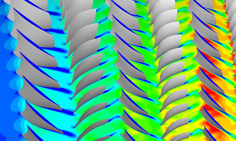
This is not easy. The quickest way is to google for pictures of compressor flow CFD results, like the one below. The full resolution picture can be found here.

CFD picture from a compressor cascade simulation

Generally, these rules apply for compressor airfoils:

  • They should not block the flow path, so their thickness is minimized.
  • Their angle of attack range is small, so they do not need a big nose radius.
  • They must produce the maximum flow deflection possible, so their camber is higher than that of most wing airfoils.

The closest thing to a compressor airfoil you can find on a wing is the airfoil of a Fowler flap. Like the compressor blade, it sees almost no angle of attack variation, can be made thin because it is supported every few meters, and needs to produce as much lift as possible.

Note that due to the rotation, any buildup of a thicker boundary layer is prevented by centrifugal forces, which will eject that boundary layer outwards. This allows to use more camber.

$\endgroup$

You must log in to answer this question.

Not the answer you're looking for? Browse other questions tagged .