No, this is only an approximation based on the assumption that the L/D ratio is fairly high. Imagine that the glider has a gigantic drogue chute attached, so that the flight path is aimed almost straight down. Almost all the aircraft's weight will be borne by the drag vector, and almost none of the aircraft's weight will be borne by the lift vector. The weight vector will be almost parallel to the flight path and the total "power" exerted by gravity will be equal to weight * descent speed, which will be almost equal to weight * airspeed.
If the glider (w/ drogue chute still attached) now powers up a powerful motor (guess it was a motorglider) and tries to fly horizontally, why should we expect the minimum power needed to maintain altitude to be equal to weight * the descent speed from the power-off case?
Here is the key to seeing why when the L/D ratio is poor, the horizontal flight case takes much more power than the gliding case:
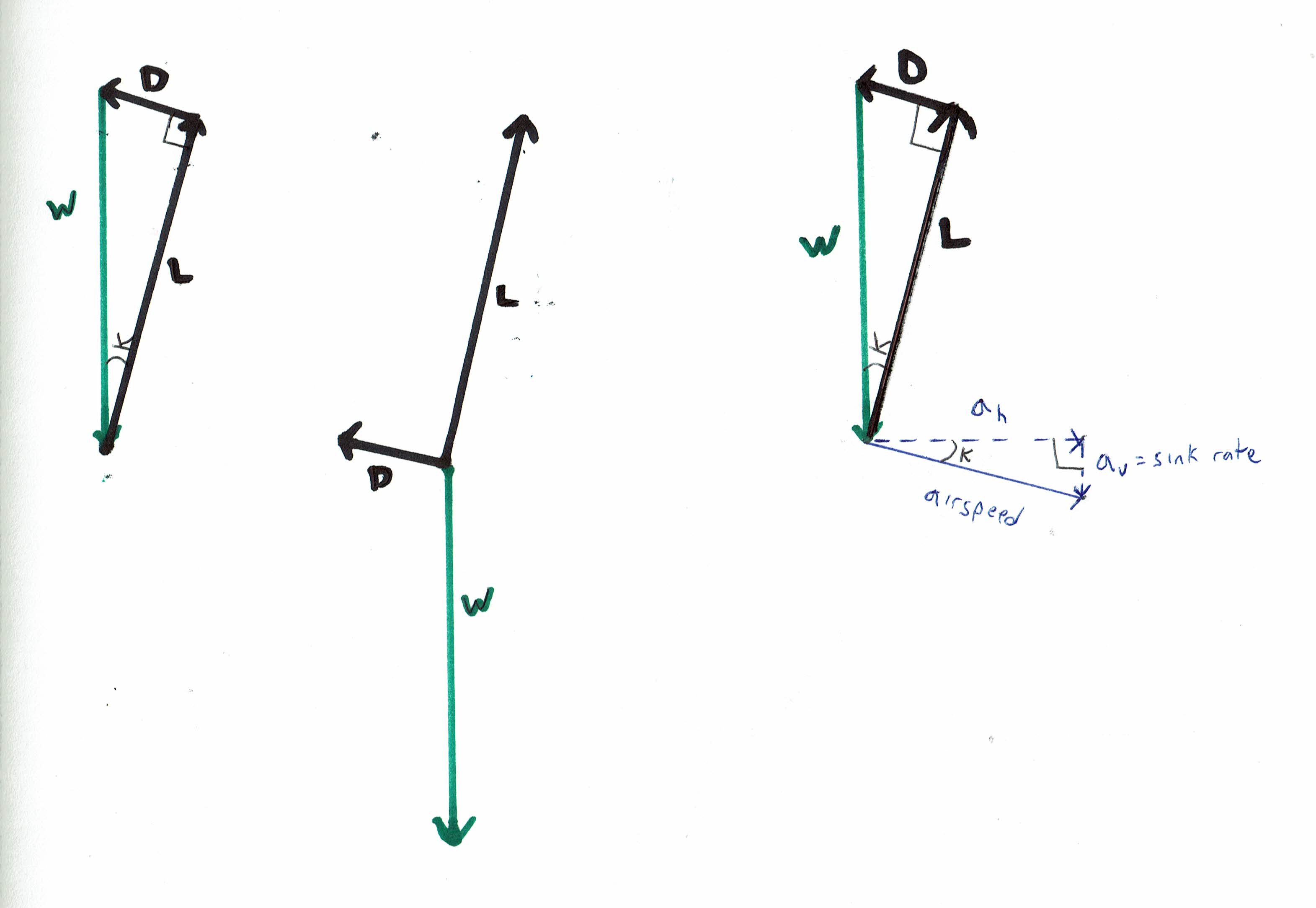
The balance of forces in gliding flight can be represented by a closed vector triangle of Lift, Drag, and Weight, with right angle between the Lift and Drag vectors. If we wish, we can also show the airspeed vector, and we can break it down into its horizontal and vertical components. The vertical component of the airspeed vector is simply the sink rate.
All three of the vector diagrams below represent the exact same physical situation. We've represented the aerodynamic forces in black, and the gravitational force-- the weight vector-- in green. The left-hand and right-hand diagrams are easier to understand than the middle diagram, because the force vectors are arranged into a closed polygon (a triangle in this case), which shows us instantly that the net force is zero. On the right-hand diagram, we've also included the airspeed vector, and it's horizontal and vertical components. Note that K is the glide angle, and note that on the right-hand diagram, the triangle formed by the force vectors and the triangle formed by the airspeed vectors are similar triangles.
The lift vector is proportional to the lift coefficient times the airspeed squared. The drag vector is proportional to the drag coefficient times the airspeed squared. The ratio between the magnitude of the Lift and Drag vectors is identical to the ratio between the lift and drag coefficients. For a given fixed aircraft shape, a change in the lift coefficient and/ or drag coefficient represents a change in angle-of-attack. Every possible angle-of-attack of the wing is associated with a specific lift coefficient, a specific drag coefficient, and a specific Lift : Drag ratio. This is true regardless of whether the aircraft is heavy or light-- a change in weight is expressed as a change in the airspeed associated with any given angle-of-attack, but no change in the lift coefficient, drag coefficient, or Lift: Drag ratio associated with any given angle-of-attack.
What happens when we change the lift coefficient and/ or the drag coefficient, causing a change in the ratio of lift coefficient to the drag coefficient, which causes an identical change in the ratio of Lift to Drag?
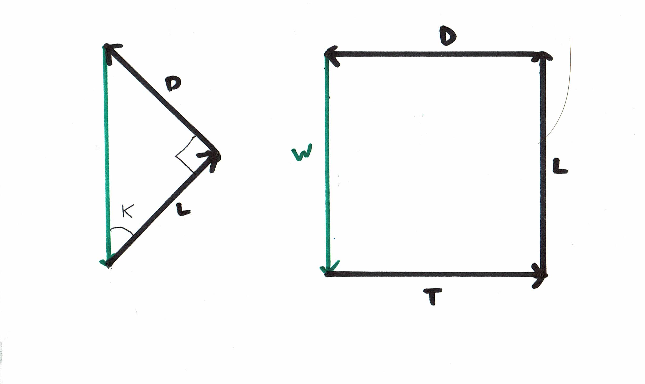
The left-hand diagram above represents a Lift to Drag (L:D) ratio of 10 to 1, while the right-hand diagram above represents a L:D ratio of 1 to 1.
When the L/D ratio is high, L is very nearly as large as W. But when the L/D ratio is low, L is much smaller than W.
When we start from the gliding case w/ a low L/D ratio, and then add thrust to maintain horizontal flight, what must happen? How must we modify our vector to diagram so that the force vectors still form a closed polygon (in this case a rectangle or square), indicating that no net force is acting on the aircraft?
Take a pencil and paper and draw the L-D-W vector triangle for such a case-- where the L/D ratio is very poor. Now to change the picture to represent the powered case, you have to take the L and D vectors, keeping the 90-degree angle between then, and pivot them (e.g. counterclockwise in the diagrams attached to this answer, and also in the diagram attached to the original question) until the D vector is horizontal and the L vector is vertical. Then you must EXPAND the L and D vectors, keeping the same proportion between them, until the L vector is fully as large as the W vector, so L is equal and opposite to W.
Like this:
What is really going on when we EXPAND the L and D vectors in this manner? Assuming that our angle-of-attack is staying constant, meaning that our lift coefficient and drag coefficient are both staying constant, this EXPANSION of the L and D vectors can only represent an increase in airspeed. The airspeed must increase according to the square root of the increase of the size of the L and D vectors.
Here's one way to understand why the airspeed is lower in the gliding case-- the Drag vector is supporting part of the weight of the aircraft, and this "unloads" the wing, compared to the horizontal case. Flight at a lower wing loading requires less airspeed than flight at a higher airspeed.
The exact same thing happens we take the aircraft with the high L/D ratio-- as illustrated in the left-hand diagram above-- and add thrust to allow level flight. The magnitude of the Lift and Drag vectors, and the airspeed, all must increase. But if the L/D ratio is high, the effect is so small as to be negligible, and we can say that the airspeed observed during a glide at a given angle-of-attack is nearly identical to the airspeed observed in powered flight at the same angle-of-attack, and we can also say that the Drag force in horizontal powered flight is virtually identical to the Drag that is present in gliding flight.
When the L/D ratio is high, why does the power exerted by gravity have anything to do with the power an engine would need to exert to allow horizontal flight?
Work is proportional to force times distance, and power is proportional to force times velocity. Drag is the only aerodynamic force that is opposing the aircraft's forward airspeed, so Drag is the only force that needs to be overcome to allow forward flight, regardless of whether the aircraft is flying horizontally or gliding downward. (And note that from the standpoint of the airmass reference frame, a glider is ALWAYS gliding downward.) In the gliding case, what force is opposing Drag? We can break the Weight vector down into one component that is equal and opposite to the Lift vector, and one component that is equal and opposite to the Drag vector. The latter component is what is "powering" the glider, at least as viewed from the standpoint of the airmass reference frame. The latter component of the Weight vector will be equal to Weight * cosine (glide angle). So the Power exerted by this component of the Weight vector is equal to (Weight * cosine (glide angle)) * airspeed). Now, it just so happens that the sink rate is equal to (airspeed * cosine (glide angle)). So we can say that the power exerted by gravity = (Weight * cosine (glide angle)) * airspeed) = (Weight * (cosine (glide angle)) * airspeed) = Weight * sink rate.
If the L/D ratio is high enough that for any given angle-of-attack, the "unloading" of the wing in gliding flight due to the drag vector is negligible, the airspeed obtained at that angle-of-attack will be nearly identical in horizontal flight as in gliding flight, and likewise the magnitude of the Drag vector will be nearly identical in horizontal flight as in gliding flight, so our expression (Weight * sink rate) will only underestimate the power required for horizontal flight by a negligible amount. On the other hand, if the L/D ratio is poor, then the drag vector will greatly "unload" the wing in descending flight, and the airspeed obtained at that angle-of-attack will be much less in gliding flight than in horizontal flight, and the magnitude of the Drag vector will be much less in gliding flight than in horizontal flight, so our expression (Weight * sink rate) will greatly underestimate the power required for horizontal flight.
Note that it's also true that in a powered climb, the wing is "unloaded", allowing flight at a lower airspeed that we'd see at the same angle-of-attack in horizontal flight. In this case it's the excess thrust vector (thrust minus drag) that bears part of the aircraft weight. A jet fighter climbing steeply in a near-vertical climb is generating very little lift, so either the airspeed must be low, or the wing must be presented to the air at a much lower angle-of-attack than would be the case during horizontal flight at that same airspeed.
For the power-off case, the truth is that most aircraft have a shallow enough glide path that the effects we've described above can be ignored, and the expression (weight * sink rate) does indeed give a good approximation of the power required for level flight. For example, consider an aircraft with a L/D ratio of 8:1 at idle power at some given angle-of-attack. In still air, the aircraft can glide 8 feet forward from every foot of altitude it loses. The glide angle at this angle-of-attack is equal to arctan (1/8) = 7.1 degrees, and the lift vector is equal to weight * cosine (glide angle) = weight * cosine (arctan (1/8)). This works out to weight * .9923. So there is less than a 1% change in the magnitude of the lift vector (and the same for the drag vector) between the idle-power case, and the case where aircraft is generating enough power to fly horizontally at that same angle-of-attack. This means the airspeed need only change by a factor of (square root of (.9925)). or .9961 . The power expended (equal to drag * airspeed) will change by a factor of .9961 * .9925 = .9886. That's pretty small.
If we are talking about an aircraft with the glide angle of a brick-- like an aircraft with a L/D ratio of 3:1 or 2:1-- then the difference would be much more significant.


