1
$\begingroup$

both M1 Abrams tank and T-80 tanks have free shaft gas turbine engines and both of their engines have variable stator vanes in their power turbine part. It says in the picture below that these variable stators exist to prevent engine damage during gearshifts. How could variable stators prevent engine damage during shifts? By the way, PCA talked about in the picture is the automatic fuel injection system that regulates fuel injection during gear changes.

There is no clutch mechanism in the traditional sense in the transmission of the T-80 tank. Its role is played by the above-mentioned PCA. When changing gears, the PCA pedal is moved to a stop. In this case, the nozzle blades rotate 70-80° from the position corresponding to the maximum tractive power of the turbine, which actually leads to its stop (zero power position). Moreover, it is possible to move the voter lever only when the PCA pedal is depressed, since in the initial position it mechanically and electrically blocks the hydraulic servo gearshift. Thus, the guaranteed protection of the turbine rotor from misuse is ensured. By the way, the absence of such a mechanism in the GTE-ZT engine of the object 167-T led to the destruction of the turbine blades during the tests.

Also a picture of the AGT-1500 from M1 Abrams where it also shows the variable power turbine stator blades:

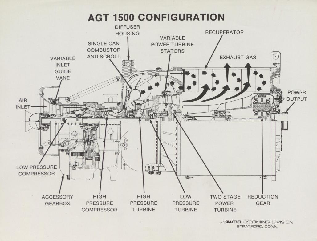
enter image description here

$\endgroup$
3
  • 2
    $\begingroup$ As asked, this question is unrelated to aviation. Please edit so that it has some cognizable tie to the subject of this exchange. "Gear shifts" are used with the transmission of battle tanks, but not as much with aircraft engines. $\endgroup$
    – Ralph J
    Commented Mar 2, 2023 at 17:20
  • $\begingroup$ @RalphJ It isnt directly releated yeah but its still very much so releated to jet engines etc thats why i thought it would still be appropriate to post it. Because this is basically same engine construction as turboshaft engine in a helicopter. $\endgroup$ Commented Mar 2, 2023 at 17:25
  • $\begingroup$ @sophit partially yeah, but the answer below by John K provided all the answers i was looking for. $\endgroup$ Commented Mar 2, 2023 at 18:00

1 Answer 1

7
$\begingroup$

When you take a turboshaft engine and subject it to large and sudden load changes, that it doesn't have to cope with in an aircraft, like during gear ratio changes in a tank, you get very sudden reductions or increases in power turbine RPM as the torque demand fluctuates.

The airflow having a lot of inertia, sudden changes like that create large changes in local angle of attack (AOA) of the power turbine blades themselves. The blades become unloaded from a reduction in AOA, or conversely they become too loaded from a sudden increase in AOA and can aerodynamically stall.

These changes in airflow at the power turbine effects the upstream flow, disrupting it, and when you disrupt the airflow in the gas generator section (the compressor/burner/HP-LP turbines), you can get compressor stalling, leading to surging of the gas generator, leading to loss of control of the flame in the burner can (which is contained by creating a boundary of cooler air around the flame using vent holes), leading to too much heat leaving the burner can, leading to overtemps in the HP/LP/power turbines. And thus the engine gets damaged.

So the variable stator vanes are to compensate for sudden flow changes from sudden changes in torque load on the turbine caused by having to deliver power though a gearbox with different gear ratios, by redirecting the incoming flow to keep the angle of attack on the power turbine blades within an ideal range.

If you built a tank with a Continuously Variable Transmission, where you can set a constant engine RPM and only vary it gradually, you'd be closer to an aircraft turboshaft/turboprop environment and you could probably dispense with the variable stators for the power turbine.

$\endgroup$
9
  • $\begingroup$ I wonder if hydraulic drive would help. $\endgroup$ Commented Mar 2, 2023 at 18:52
  • $\begingroup$ The transmission is hydromechanical, there's a fancy name for it, and the engine is probably connected through a torque converter, but it has 4 distinct fwd gear ratios and the key is being able to vary torque to the tracks while allowing the engine to wind up and down at its own pace. The power turbine stators probably give the Lycoming turboshaft in the M1 almost piston engine throttle response. $\endgroup$
    – John K
    Commented Mar 2, 2023 at 20:03
  • 1
    $\begingroup$ @JohnK Yeah the first picture is for T-80 and the second picture is for T-72 which has nearly identical transmission. Only difference is in T-80 BKP they deleted a planetary gearset and used the leftover space to reinforce the brakes and clutches to handle the big torque of gas turbine. Otherwise their BKPs are same. M1 has hydromechanical because it also has torque converter. In russian literature any transmission coupled to a TC is referred as hydromechanical transmission. Maybe in English it is referred as hydrokinetic im not sure. $\endgroup$ Commented Mar 3, 2023 at 11:15
  • 1
    $\begingroup$ Also a picture of the M1 Abrams transmission X1100 , TC is visible as well media.discordapp.net/attachments/630092657972084746/… $\endgroup$ Commented Mar 3, 2023 at 11:16
  • 1
    $\begingroup$ excellent answer, +1, thanks for sharing it here. -NN $\endgroup$ Commented Mar 3, 2023 at 18:03

You must log in to answer this question.

Not the answer you're looking for? Browse other questions tagged .