3
$\begingroup$

Consider a piston engine equipped with a turbocharger.

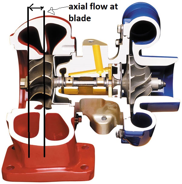
In the turbine section of the turbocharger, the pressurized exhaust airflow comes from the center (radially) to the blades, then changes direction 90 degrees, leaving the blades in axial direction in turbine. (I think airflow maybe half or last 2/3 of blade travel in axial direction?)

What does the pressure distribution at the radial turbine blade look like? Does the airflow transfer force to the blades using the same principles as on airfoil/wing, where the airflow accelerated over the upper surface of the wing creates low pressure and decelerate at high pressure side ?

enter image description here

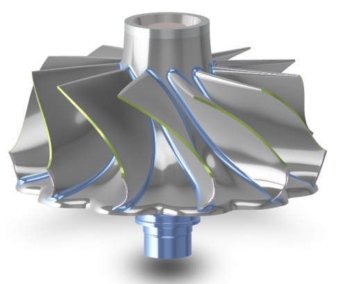
enter image description here

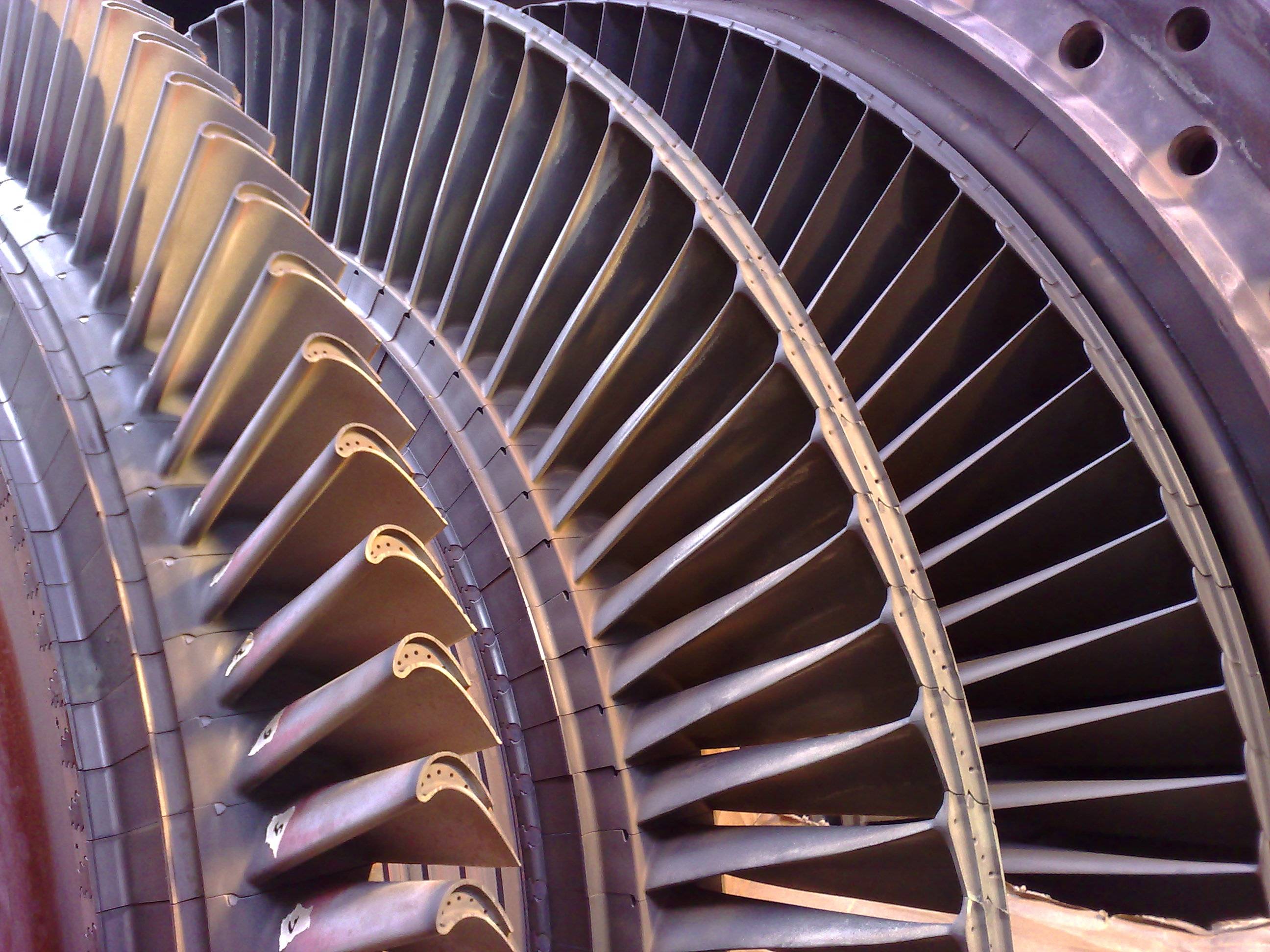
I know in axial turbine(picture below),every blade is like "small wing", operate identical as wing in aerodynamic sense, obviously without tip vortex because of blockage of housing

enter image description here

$\endgroup$
4
  • $\begingroup$ please add the sources of the images you've used $\endgroup$
    – user14897
    Commented Nov 12, 2021 at 11:51
  • 1
    $\begingroup$ The image looks like the pressurized exhaust comes from the circumference and flows into the centre on the turbine. The same is true of the early turboject engines that had centrifugal turbines. $\endgroup$
    – Jan Hudec
    Commented Nov 12, 2021 at 11:57
  • 1
    $\begingroup$ @JanHudec: Yes. Better drawing. The turbine works like in a Francis design for water (radial then axial). $\endgroup$
    – mins
    Commented Nov 12, 2021 at 16:13
  • $\begingroup$ Please note that the seemingly obvious conclusion obviously without tip vortex because of blockage of housing, is completely wrong since there are geometrical gaps to minimize the risk of contacts between rotating and static parts of the engine. In thurbomachines, this is often called the tip-clearance vortex or tip-leakage vortex. See nasa.github.io/JHU-PIV-data/static/documents/… for further information. $\endgroup$
    – BambOo
    Commented Aug 14 at 13:46

1 Answer 1

3
$\begingroup$

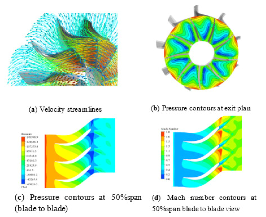
Simulations of pressure and flow conditions over radial turbine blades can be found in this article:

Design and Optimization of a Radial Turbine to Be Used in a Rankine Cycle Operating with an OTEC System

While the article is focussed on Rankine cycle, the images in the article can be considered a good general presentation of radial turbine flow conditions:

figure 18

As can be anticipated, the pressure is highest at the base/inlet portion of the turbine, and as the gasses travel towards the exit of the turbine, increasing velocity and curvature of the blades will lead to drop in pressure.

$\endgroup$

You must log in to answer this question.

Not the answer you're looking for? Browse other questions tagged .