Your question:
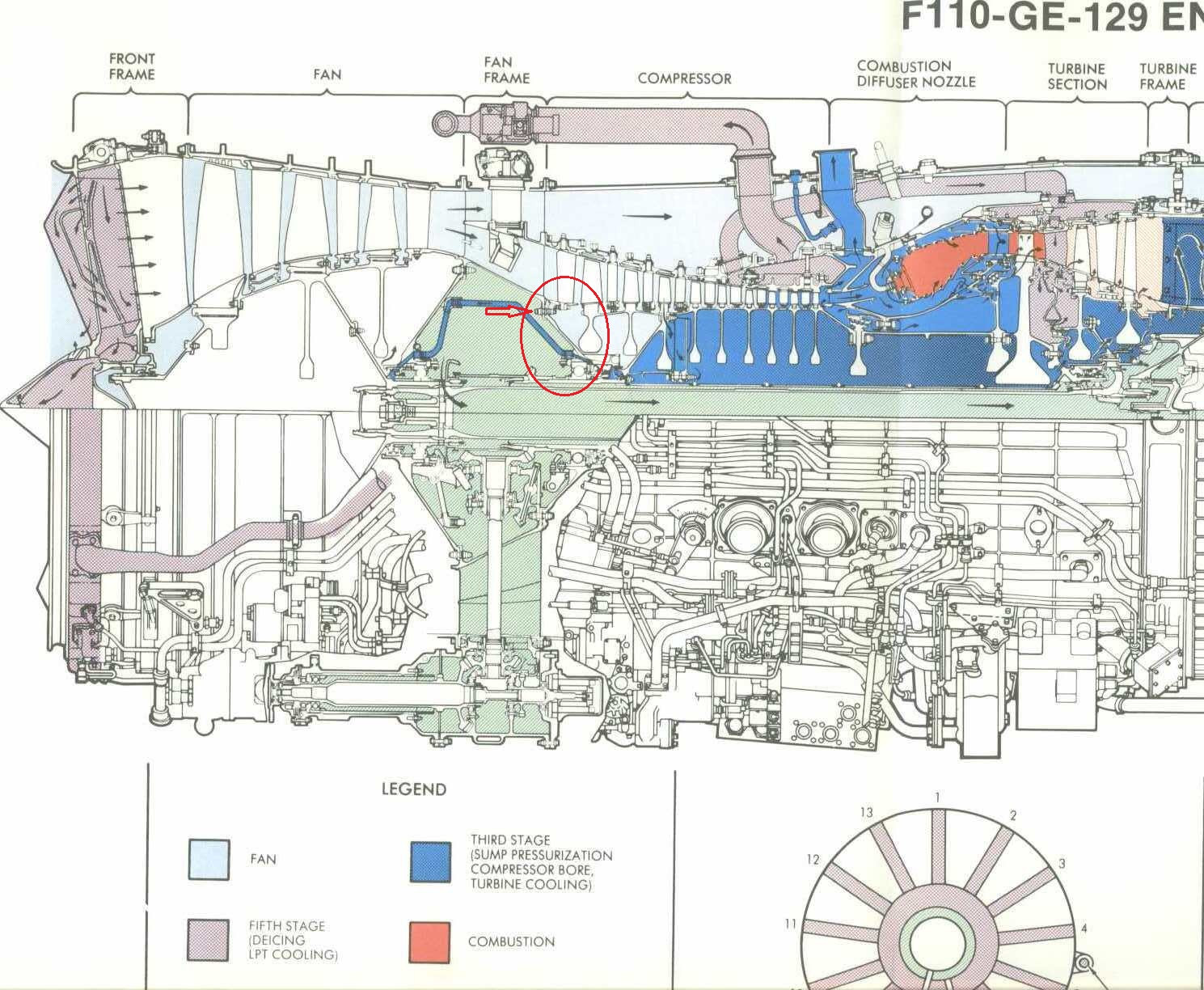
Here is a section view of a sample and I indicated the connection
area.
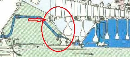
What type of connection elements are used there? Anything
related will be helpful.
From the title of your question I guess you assume the bolted element is a HPC rotor, and you might be wondering why a rotor would be bolted to a stationary element, the fan frame.
Indeed this would make no sense, and the explanation is the area you point to is not a HPC rotor but the rear seal support of the forward sump, a stationary element which role is to contain oil within the sump. The linkage is indeed a series of bolts.
The explanation below is related to this sump seal, but as you will see it also incidentally explains how disks are connected to the shaft as this plays a role in the sealing.
Rotors in the engine are centered within two frames, the fan frame and the turbine frame. The fan frame in addition has the role of transferring engine thrust to the wing. These two functions (centering and load transfer) are implemented using bearings requiring cooling and lubrication. Oil is used, and contained around bearings by closed sumps.
Forward sump
The area in your question is the end of the forward sump, located within the fan frame. The sump contains bearings #1 and #2 at the front and #3 at the rear. Bearing #3 is actually made of a ball bearing for thrust transfer to the fan frame and the mount point on the pylon, and a roller bearing for centering the HPC shaft. Here is a view of this portion for a CFM56-7B:
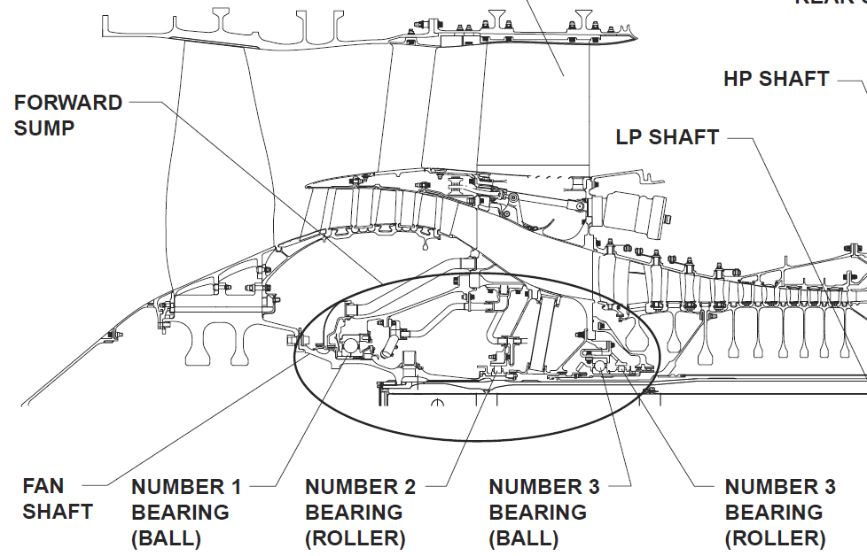
Forward sump - CFM56-7B, source: CTC 215, page 34
If you are not familiar with the bearings, sumps or seals, or the engine mounting points, the following questions will help:
Rear stationary seal
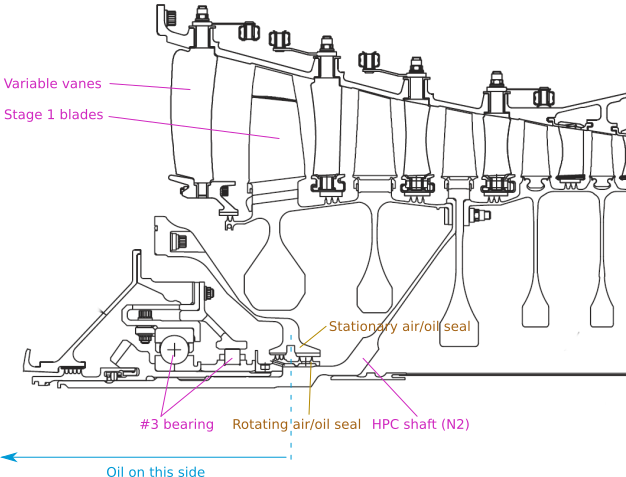
If we focus on the rear portion of the sump, we see the sump is closed by a seal between the fan frame and the HP shaft N2:
CFM56-7B, forward sump, rear stationary seal, source ibid, page 136
The seal is made of two elements: A stationary support centering seal tracks, bolted to the fan frame hub, and the labyrinth seal rotating with the HPC shaft. The bolts are the ones indicated by the arrow in your question. This looks like this:
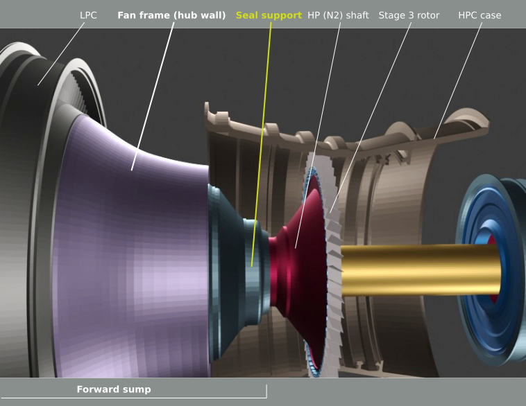
CFM56-7B rear portion of the forward sump
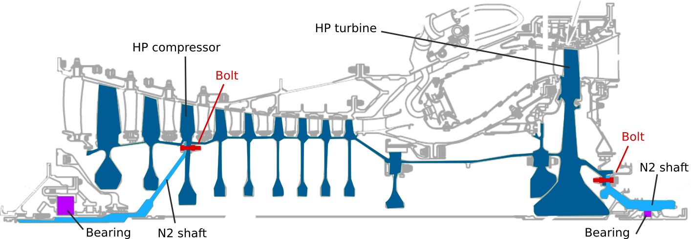
The seal support closes the sump. A part of the sump enclosure is given by the fan frame: The fan hub. Note also the red (magenta) N2 shaft which is bolted to the 3rd stage rotor and centered in the fan hub by the seal (the load is actually on the bearings within the sump).
- By the way this answers you second question about how are the HPC disks centered on the shaft. HPC rotors disks are grouped into 3 elements, stage 1-2 single spool, stage 3 disk, stage 4-9 single spool. The two spools (they look like drums) are bolted to stage 3 disk which is the only element centered on the shaft as explained above (but if you want more details, please read In a turbofan what holds the spinning axis?). Contrary to other engines, in the CFM56-7B there are no separate disks, except for stage 3, other disks (with labyrinth seal teeth and dovetail slots for blades) are cast and machined as single spools. From CTC 215 already mentioned:
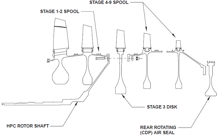
CFM56-7B HPC rotors, spools and shaft
A picture of the stationary part, with the tracks in white (that's the best picture I could find):
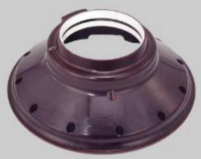
Stationary air/oil seal, source
The labyrinth rotating ring is fixed to the IGB horizontal bevel gear sleeve which is used to spin the accessory box.
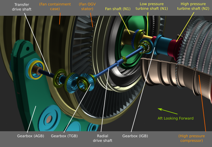
IGB location, source
In the picture above we can see:
- The HPC shaft (red) with its conical front end bolted to the stage 3 rotor of the HPC.
- The IGB gears (blue), the horizontal one being fixed to the shaft
- The sump cavity (green).
The stationary seal just close the green cavity by linking the shaft to the fan frame (the frame has been removed to show the sump).
See this answer for more.
Oil is prevented to leave the sump by the labyrinth teeth, but this is not perfect, so air is also injected into the labyrinth to push oil back into the sump. There are holes in the labyrinth ring to let air in and oil out. Air and a bit of oil fog not eliminated by the centrifugal filter are drained into the center pipe running up to the exhaust where they mix with hot air from the turbine (path used is indicated on the drawing in your question by arrows).
From Airbus, the role of the seal is:
The rotating air/oil seal provides the sealing of the aft end of the
forward sump and acts as a locknut for the No 3 bearing.
Holes between the two aft seal teeth allow passage of sump
pressurizing air. Holes passing underneath the forward seal teeth
allow oil to be drained into the No 3 bearing cavity.
The rotating air/oil seal has internal threads for installation onto
the horizontal bevel gear and its front

