10
$\begingroup$

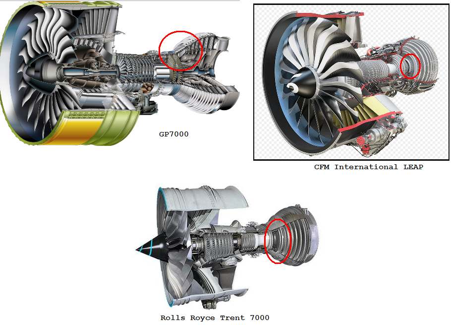
After browsing around a while, I noticed that many...I think almost all...large turbofans have this gap between the LP turbine and HP turbine. I took some screenshots and put a red circle around the gap.

enter image description here

Why do they have this gap? It's certainly not for the combustion chamber. That part comes before the LP turbine. The only thing I can think of is the LP and HP are on different spools so maybe they need some space for the bearings to brace the two shafts. But there should be bearings bracing the shaft all along its length so idk.

I'm guessing it would be more efficient to eliminate this gap and should allow a smooth transition from high pressure to low pressure. At the very least it would save some room at the end of the engine, shortening its length and maybe saving some weight.

EDIT: At first I thought it was totally empty. But it appears that space has stator vanes not shown in the pictures. I'm editing the title with the phrase "gap of turbine blades" because the original spirit of the question was about way there's a big space between the two sets of turbine blades. The space happens to have something else in it, but not turbine blades and I was wondering why those sets are separated.

$\endgroup$
1
  • 3
    $\begingroup$ Because the fan runs at a much lower RPM than the compressors, so for a un-geared LP turbine to fan link the LP turbine needs to run at the same lower RPM. As a result the HP and LP turbine has a much difference in diameter so you need some space for the diameter transition. Filling the gap with either LP or HP blades doesn't worth the weight or complexity. Some turbofans has geared LP turbine to fan connection so the LP turbine runs at a much higher RPM hence a smaller diameter, then you won't see the gap on them. $\endgroup$ Commented Aug 29, 2017 at 20:08

3 Answers 3

13
$\begingroup$

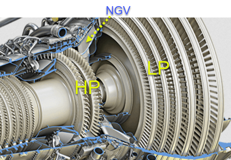
enter image description here
(Source) Cutaway for the GE9X.

The gap you see is not empty. Marked above is one of the nozzle guide vanes (they have removed most of them for illustration purposes). Those vanes are analogous to the compressor stator stages.*

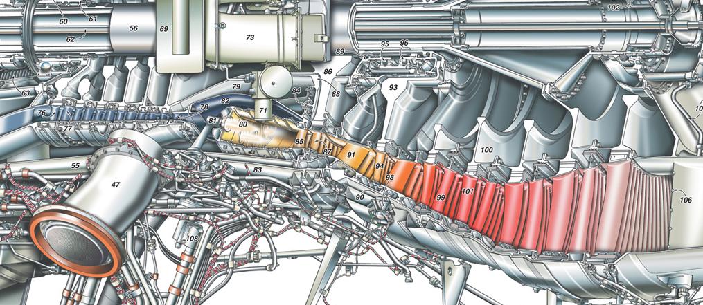
Labels 91 and 99 below are those vanes—sadly the stators and vanes are almost always omitted from 'drawings', yet they are as important.

enter image description here
(Source) Turbine stages of the RR Trent 500.

The reason why the diameter difference is steeper in the GE compared to the RR, is because the RR Trent 500 is a 3-spool engine.

In short, the vanes in both engines when omitted from drawings, give the illusion of there being a gap (wasted space).


* Nozzle guide vanes have nothing to do with the propelling nozzle at the rear. In turbine lingo, nozzle means the stator stage for the turbine.

On the funny side, here's a thumbnail from RR's own YouTube channel, absolutely bonkers exhaust. Don't trust illustrations.

$\endgroup$
1
  • $\begingroup$ Concerning the "nozzle" .. the function of the nozzle is in both cases similar - in the turbine exit, it's to "convert" pressure to velocity (plus directing it as desired - rearwards), for increased momentum hence thrust. In the guide vanes it's the same, best to mentinon on the first turbine vane: relatively slow, high pressure flow from the combustion chamber gets expanded & accelerated in Vane Row 1 & sent in the desired direction (strongly circumferential), for maximum momentum on Blade Row 1. That centerfire spacecraft nozzle in the RR engine is indeed hilarious $\endgroup$
    – Apfelsaft
    Commented Dec 15, 2022 at 10:10
7
$\begingroup$

@ymb1 is correct that there is an aerodynamic function of the LPT nozzle in that space, but there is also a mechanical function as well. You correctly observed that there will be bearings supporting the shaft. But what supports the bearings? They are not just floating out there in space. The bearings are supported by a frame.

On the GP7200 and CFM LEAP, there is a frame between the HPT and LPT that is referred to as the "turbine center frame". The function of the frame is to provide a stiff loadpath from the bearing that supports the aft end of the HP shaft up to the main structure of the engine that connects to the aircraft. If you check this post, you'll see plenty of examples for the frames.

$\endgroup$
0
7
$\begingroup$

Short answer

This space is part of the inter-turbine duct (ITD), a duct which is required to maintain a satisfactory flow continuity between HPT and LPT rotating at different speeds (in the ratio of 1:3) and having different diameters. The duct is made of the gap and the larger (in the axis direction) LPT stage 1 vanes.

Note this duct is a diffuser as the annular area is growing along the flow path. What happens in this diffuser is not very well known and its design has been empirical to some extend, using guides like this:
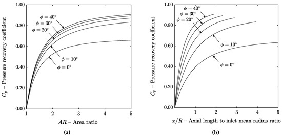
Diffuser, pressure recovery vs friction
Pressure recovery vs friction. Source

Some numerical simulation demonstrated the design indeed influences the LPT (pressure loss in the duct), but also the HPT and the combustion. On days where saving 1% fuel (therefore 1% CO2) is important, some effort is now done on the optimization of the inter-turbine duct.

Shortened ITD are complex to design and known under the name of aggressive ITD.

Details

Taking the CFM56-7B (Boeing 737 NG) as an example. This engine has a single stage HPT and a 4 stage LPT.

Each rotor is preceded by stator (nozzle). The role of the stator vanes is to convert pressure into velocity and turn the flow more perpendicular to the rotor blades surface. This is opposite to the compressor stages where the vanes are downstream of the blades to convert velocity added by the blades into pressure, maintain velocity constant and straighten the flow.

Gap and larger vanes

Everything is globally continuous, though there is a a gap forward of the LPT stage 1 nozzle located in the HPT casing. The vanes themselves are larger axially.
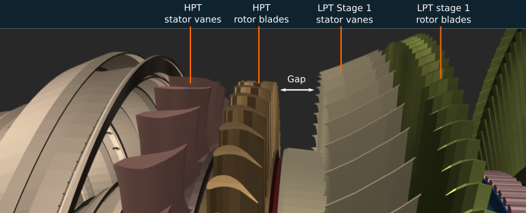
CFM56-7B, small gap before LPT Stage 1 vanes

This location is called the inter-turbine (transition) duct, it corresponds to the interface between HPT and LPT which are rotating at different speeds.

The duct has an increasing area due to the larger diameter and size of the LPT stage 1 rotor (a similar duct exists between LPC and HPC for the same reasons).
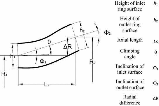
enter image description here
Inter-turbine duct geometry. Source

The gap is chosen to set (empirically) the adequate duct slope, aspect ratio, etc for an acceptable pressure loss between the turbines.

To increase engine performance, manufacturers are trying to decrease the length of the duct but there is a lack of knowledge in this domain.

Shorter ducts are known as aggressive inter-turbine ducts (AITD). See this paper.

Bearings

Regarding the reason mentioned in another answer, a possible problem with a bearing or a bearing support in the way: This is not actual, the bearings are much smaller than the turbine stages:
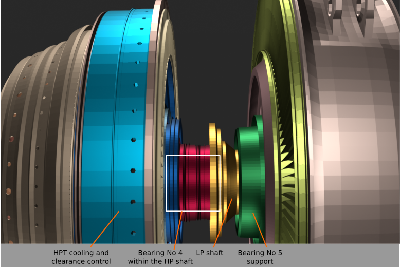
CFM56-7B, location of rear bearings

  • The No 4 bearing is between the HPT shaft and the LPT shaft.
  • The No 5 outer support is within the oil collector, and the bearing itself is within the its support.
$\endgroup$

You must log in to answer this question.

Not the answer you're looking for? Browse other questions tagged .