TL;DR
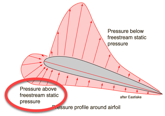
- In most cases the pressure distribution on the pressure-side is higher than on the suction-side (with respect to the chord-wise location).
- There is not general answer to this question since the pressure distribution on the pressure-side is (although mostly close to static ambient pressure) connected to the profile shape.
- For low velocities the pressure on the pressure-side is likely to be very close to the ambient static pressure.
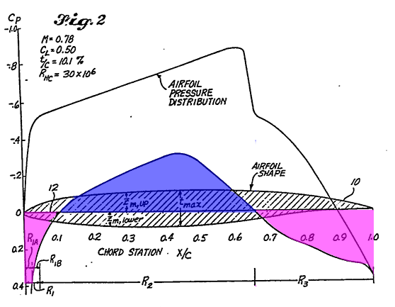
Comment on the Figure 2
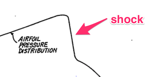
The depicted airfoil is operating in the transonic-regime. This means the free stream velocity is close to the speed of sound (M=1). Caused by acceleration of the air on the suction side of the profile the air flow will reach supersonic speeds. The rapid increase in $C_p$ at the suction side is a shock.
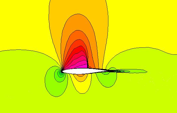
The following picture shows the Mach-number-distribution around an airfoil in the transonic speed range.
Comment on compressibility
The term $\frac{1}{2}\rho V^2$ is a representation of the dynamic pressure for very low velocities (M<<0.3). Of course this equation can also be used for higher Mach-numbers, however the results (in terms of self-similarity) will contain a large error. Therefore, $p_0 - p_\infty$ should be used to avoid this.
Comment on the pressure distribution on the pressure-side
During level flight (design-speed@design-AoA) there will be a stagnation zone at the leading edge of the airfoil. This results in a pressure higher than the static free-stream pressure. After that the flow will be accelerated resulting in a reduction of the pressure. Often, this reduction will result in a $C_p<0$.
At the trailing edge the pressure of suction- and pressure-side have to be equal, so the pressure rise of the aft-section of the airfoil-pressure side will be adjusted accordingly.
Answer:
For low Mach-numbers (e.i. low free stream velocities) the pressure on the pressure-side is likely to be very close to the ambient static pressure.
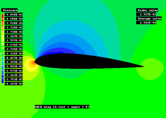
Comment on low-pressure-region on the pressure-side
As always with the (elliptic) aerodynamics it's a bit chicken-and-egg. Lets assume (Caution! this is a very simple point of view) there is only one design objective (lift). Then the pressure-distribution on the pressure side needs to fulfil two boundary conditions. 1) high pressure ($C_p$) at the leading edge which is a result of the free stream velocity and 2) the pressure ($C_p$) at the trailing edge which is given by the pressure-distribution on the suction-side. Now, the airfoil-designer needs to find a profile-shape which fulfils both requirements. Whether the $C_p$ becomes negative or not is not of importance, as long as it stays above the $C_p$ of the suction-side and there is no risk of boundary-layer-separation (which is likely to cause missing the pressure at the trailing edge).
Since there are no simple answers to complex problems, I truly beliefe the best thing would be to install Xfoil (or its successor) and try it out.

