Going back further to the early 40's to the de Havilland Goblin turbojet:
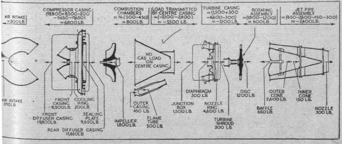
There is an in-depth article from Flight from February 21st, 1946. The first page is here, but you'll need to download the rest of the pages from the navigator on the left. It even comes with this diagram showing the forces on the different parts.

Materials
Reading through the article, the biggest unknown back then was the materials to choose for the hot sections.
Plenty of theoretical information was available on blade form, but little was known about the operating temperatures likely to be experienced. Chief properties required of the selected materials were a high resistance to creep, corrosion and scaling.
They got their hands on the strongest materials, and with the aid of heat-sensitive paint, they scaled back the requirements.
On the first few engines, turbine discs were made of austenitic steel, but later, with the aid of heat-sensitive paint, it was found that ferritic steels with their greater strength, around the working temperature of 750 deg. C. and a lower coefficient of expansion, would prove satisfactory.
Vibrations
For vibrations, what I gather is it's not that big of a deal for turbojets compared to turboprops of that era, but here's the relevant part:
[...] subsequent measurements of vibration for the whole power unit have shown that the vertical oscillation is less than ± 0.001 inch.
Trial-and-error
There is also the test-to-destruction method (not really):
[...] troubles experienced included weaknesses in the welding of combustion chambers, and in the construction of the intake ducts and the tail pipe.
So, there was a fair share of trial-and-error.
Forces
Regarding the forces, and that's a guess here, we find:
Any thrust loading is taken by the front bearing which is located on a stub or pivot shaft between the air intake ducts in front of the impeller.
Post-examination of the bearings may yield information.
For gas-load calculations, back then they've already made very powerful turbocharged engines, so they've had the knowledge. As the article suggests, the chief issue was the materials.

