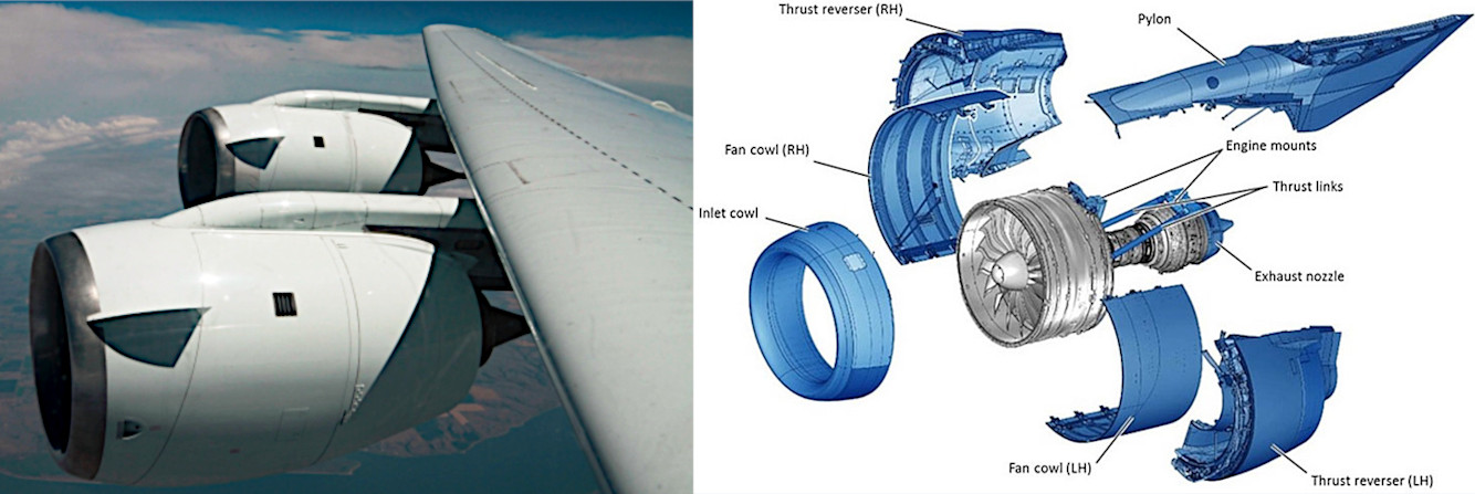
When the turbofan is spinning inside the housing, what holds the axis? All I know is that the axis holds the fan blades.
4 Answers
Stationary frames
The supporting structures of a turbofan are two stationary frames with their characteristic struts, located at the ends of the engine core: One is behind the OGV stator of the fan module, the other at the aft end of the turbine module:
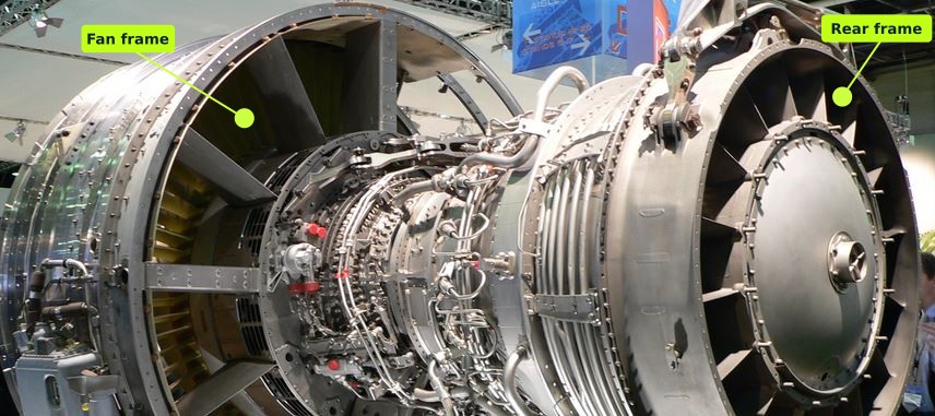
CFM56 with the two frames visible (source)
Stationary frames to spinning shafts
In the case of an engine with two spools, the frames support the longest shaft (N1, low pressure), which in turn supports the coaxial N2 shaft (high pressure).
Shafts are centered within frames by bearings (drawn in magenta in the next picture).
Shaft to rotors
Disks of rotors on a spool are bolted together to form a continuous structure fixed to the related shaft. The structure is used as the inner wall for the related air duct:
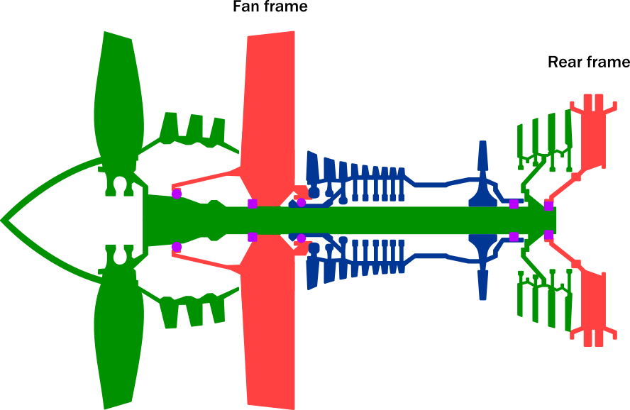
Frames, shafts, bearings. Adapted from CFM56-7B Familiarization Manual
A view of the N1 shaft and the two frames, before adding the bearings and their oil sumps. The fan shaft (darker / trumpet-shaped) is fixed to the N1 shaft using grooves and can be considered part of the N1 shaft:

LP shaft, fan frame and turbine frame of a CFM56-7B
The bearings and the oil sumps are added to center the N1 shaft (blue tubes are used to pressurize air-oil seals of the fan sump). The clevises used to hang the engine under the pylon strut are (barely) visible on the top of the rear frame (see this question for details):

LP shaft, fan frame, turbine frame, bearings and sumps of a CFM56-7B
Another CG view which additional elements:
The fan disk bolted on the N1 shaft (actually fan shaft).
The fan cone and spinner bolted on the fan disk.
The two extremities of the N2 shaft coaxial to the N1 shaft.
The HP/N2 shaft (shown in red above) is centered on the LP/N1 shaft by bearings. All rotors of the HP spool form a single structure bolted to the HP shaft (shown in light blue below):
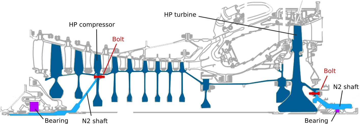
HP rotors of CFM56-7B. Adapted from CFM56-7B Familiarization Manual
Frames to core stators
Similarly, outer shrouds of stators and intermediate rings of a spool are bolted together to form continuous structures.
Four stationary structures are built:
- The LP compressor (booster) stators assembly is fixed to the mid-box of the fan frame (on the fan side).
- The HP compressor stators assembly is fixed to the mid-box of the fan frame (on the other side).
- The combustion chamber is fixed to the HP compressor assembly.
- The turbine stators assembly is fixed to the combustion chamber on one end and to the rear frame on the other end.
Overall CG view with some components highlighted:
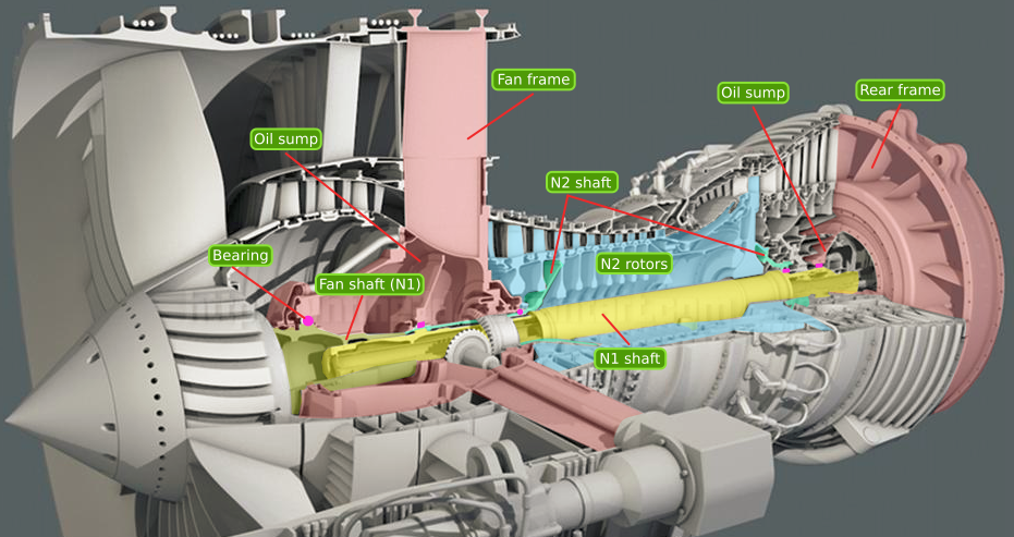
CFM56-7B cutaway. Original CG model by vhfine3d, at DeviantArt
From frames to wing strut
The engine is supported by a pylon, which is supported by the wing. There are only two mount points connected to the pylon, located on the fan and rear frames. Thrust is usually transferred to the wing using the forward mount point.
If it is not practical to transmit the thrust from the forward mount, e.g. because space is lacking to build a strong mount, then thrust links are used to transfer thrust to the aft mount which transmits it to the pylon:
Other components
There are a few other components to support.
The air inlet is fixed on the fan case.
The fan case (which role is to create a duct for the fan and contain any broken fan blade piece) is fixed on the fan frame.
The nacelle, that is the fan cowls and the thrust reversers ducts, including the reversers, is fixed directly to the pylon. The nacelle is not really part of the engine.
The exhaust nozzle and cone are fixed to the turbine frame.
To sum up
Engine component are kept together using two frames.
- Rotors are fixed to shafts, which are maintained within the frames by bearings.
- Stationary components (fan case, stators, combustion chamber, etc) are bolted together and fixed the directly to the frames.
-
2$\begingroup$ Nicely done! With some continued maintenance, we can probably start pointing most new jet engine questions at this answer and be done with it! It's not that complete, but it's close! $\endgroup$– FreeManCommented Mar 7, 2016 at 13:49
Struts. Lots of them, and with an aerodynamic shape so they don't cause too much drag. Some of those struts double as stator vanes and reduce the swirl of the internal flow. By doing this they add a little thrust. Others house the driveshafts by which rotational energy is taken from the shaft to spin pumps and generators.
Maybe it helps to watch this YouTube video. I pasted a screen shot from it below:
Jet engine cutaway. The bright orange shows where the structure has been cut. In the grey gaps you see plenty of vanes and struts: They hold the shaft bearings in place.
On multi-spool engines the outer spool is held in place by the struts and has internal bearings to keep the inner spool in place. Since the outer, high-pressure spool is shorter, the inner, low-pressure spool emerges from the outer spool at both ends.
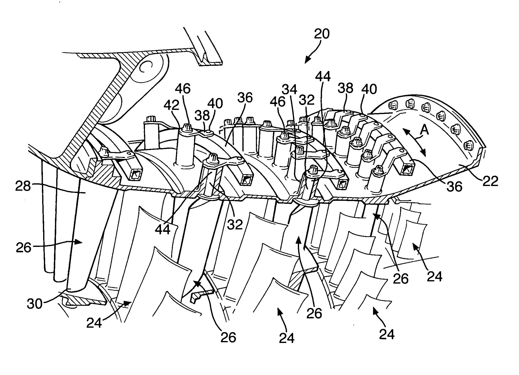
This drawing from a patent shows moveable stator vanes. They are arranged like spokes on a wheel. Each disk of stators is placed between two rotor disks.
Stator vanes (26 and 28) held moveably in place by bolts (32 and 44) and interspersed with rotor vanes (24). A lever (38) on each vane is moved by an actuator ring (36) and adjusts the incidence of the stator vanes.
-
1$\begingroup$ The movable stators don't seem to be connected (via bearings) to the shafts at all, so they don't hold anything. This doesn't answer the question. $\endgroup$– ScrontchCommented Sep 3, 2020 at 12:16
-
$\begingroup$ @Scrontch Why didn't you read the answer? Of course don't the movable stators hold the shaft - how would you think they do? $\endgroup$ Commented Sep 3, 2020 at 17:12
-
2$\begingroup$ I did read the answer, but did you read the question? I was just trying to be helpful by explaining the reason for my downvote. Of course i see that the stators don't hold the shaft. That's exactly why i'm complaining that this isn't a good answer. I don't see why you even mention them at all, let alone making them half the space of your answer. Just adds confusion for nothing imho. $\endgroup$– ScrontchCommented Sep 4, 2020 at 19:49
I'm assuming you're asking about the shaft support. In that case, the engine shaft is supported on the engine casing using bearings (the type of which may vary).
-
$\begingroup$ Yup, the spool is held in place by a number of bearings. $\endgroup$– user7241Commented Mar 13, 2016 at 20:30
I Believe the 1st picture don't show the turbine frame, but the fan frame (By the way, i'm not sure if Turbine Frame can have use of the VBV System), after some research I believe that CF6 and CFM56 have the exact same model of Fan Frame, probably they shares some other parts too... And maybe some others GE motors get shared others same parts


