There is no airfoil with good lift in both flow directions, but one with some lift is conceivable. However, the lift-to-drag ratio will be nothing to write home about.
One reasonable candidate would be created if we use the forward half of the venerable NACA 66(2)-415 and copy it again for the last half. Like that:

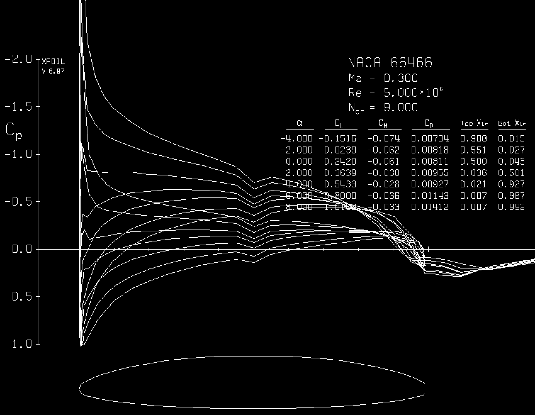
As you might recognize from the plot, this was done with XFOIL. However, the iteration does not converge. But when real air hits this thing, it will create lift, much like a cambered plate will do. Its inviscid zero angle lift coefficient is already 0.5, however, viscous effects will reduce this lift coefficient.
In a good airfoil, the pointed trailing edge defines the point for flow separation, while the rounded nose leaves it to the flow to find a suitable stagnation point. Here we have a rounded contour on both ends, so the separation point widens to a separation area, and this will creep up on the top side once the flow develops some suction at the top. Hence, lift will be poor and drag will be high.
With a little trick, XFOIL can be convinced that this is a regular airfoil with a really blunt trailing edge. Then this is the result at a Reynolds number of 5 million and Mach 0.3:

However, now the separation at the trailing edge is prescribed and will not as easily move up, so the results might be too positive. It seems that L/D exceeds 70 (which surprises me! The original 66(2)-415 has a lower L/D at the same flow conditions, which is a strong hint that we are misusing XFOIL here). Compare that to a good glider airfoil L/D of over 200 at this Reynolds and Mach number.
Applicability
I cannot think of a good reason to do this. The consequences of flying backwards include:
- What was stable previously will become unstable - in all directions! Remember that the neutral point is at the quarter chord, measured in flow direction. If the flow direction is reversed, the distance between neutral point and center of gravity will suddenly be more than half the wing chord - in the wrong direction! The same goes for the vertical, which is now destabilizing.
- This includes all control surfaces: They will run into their stops and stay at maximum deflection. A manual control system will become unusable, and even a hydraulic, computer-controlled one will experience extreme loads which overpower conventional actuators. When combined with Gurney flaps or directed blowing on both sides, the control issues should become manageable.
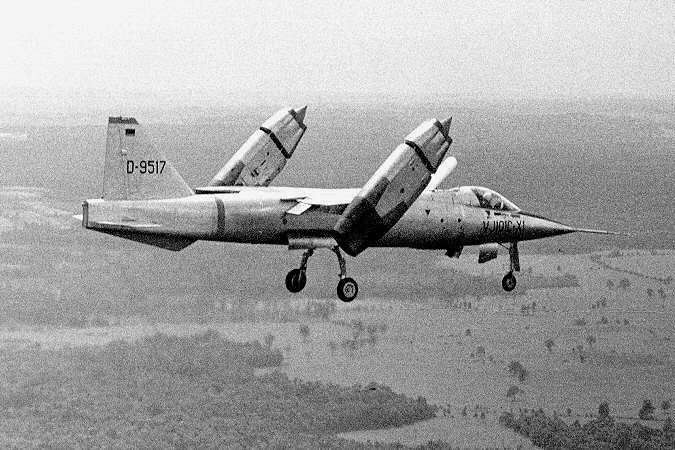
- If done with reversing a variable-pitch propeller, most of the propeller will not work anymore, because the blade twist runs now opposite to how it should. You could, however, create enough thrust if you use a VJ-101 style propulsion where the engine gondolas swivel through 180°.

VJ-101 (picture source)
EDIT: @Marius mentioned in a comment below the S-72 X-Wing, an attempt to make a helicopter go faster by stopping the rotor above a certain forward speed. The X-Wing actually used an elliptical airfoil and forced the Kutta condition by directed blowing. This enabled it also to use a rigid wing and to adjust blade lift for cyclic and collective control by blowing. This is indeed the only sensible application of an airfoil that works in both directions.
ANOTHER EDIT: I just found this on Airfoiltools.com: The Sikorsky DBLN-526 double ended rotorcraft airfoil. It was most likely used on the S-72, and its 26% would only work with directed blowing, anyway.


