8
$\begingroup$

Recently I came across a airfoil improvement called a 'Gurney flap', see image.
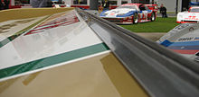
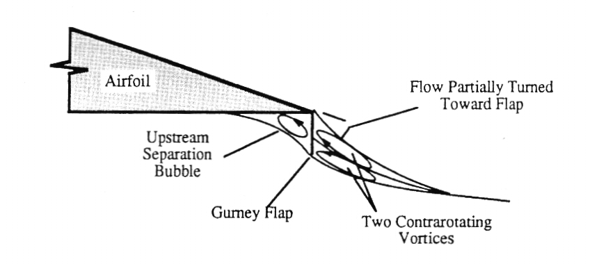
enter image description here enter image description here

I don't really understand the working principle of a Gurney. Wikipedia states:

The Gurney flap increases lift by altering the Kutta condition at the trailing edge. The wake behind the flap is a pair of counter-rotating vortices that are alternately shed in a von Kármán vortex street.In addition to these spanwise vortices shed behind the flap, chordwise vortices shed from in front of the flap become important at high angles of attack.

I don't understand how the flap could generate vortices in front of the flap. Wikipedia states the following effects:

The Gurney flap increases the maximum lift coefficient ($C_{L_{max}}$), decreases the angle of attack for zero lift ($\alpha_0$), and increases the nosedown pitching moment ($C_M$), which is consistent with an increase in camber of the airfoil. It also typically increases the drag coefficient ($C_d$), especially at low angles of attack, although for thick airfoils, a reduction in drag has been reported.

Is it simply a ridge that stops the flow, and thereby increases the pressure at the top surface?

How come the drag is decreased for thick airfoils if it generates extra vortices?

$\endgroup$
5
  • $\begingroup$ Perhaps a useful diagram of the Kutta condition: people.rit.edu/pnveme/MECE356/lift/lift_images/kutta.jpg $\endgroup$ Commented May 21, 2015 at 8:26
  • $\begingroup$ @MikeFoxtrot: The flow behind the wing is wrong on that picture and without description I don't think I would understand anything from it I didn't know already. $\endgroup$
    – Jan Hudec
    Commented May 21, 2015 at 11:54
  • 1
    $\begingroup$ I'm not sure Dan Gurney understood why or how it worked, he just knew that he got more downforce on his car when he added that little lip to the rear wing. ;) (Yes, the Indy 500 is this weekend, and it's just down the road.) $\endgroup$
    – FreeMan
    Commented May 22, 2015 at 3:49
  • $\begingroup$ This does answer a part of my question, but it doesn't talk about the drag advantages of Gurney flaps. $\endgroup$
    – ROIMaison
    Commented Dec 15, 2022 at 13:08
  • 1
    $\begingroup$ @ROIMaison: NASA tested and simulated the behaviour of Gurney flaps in the past. I find this report in particular interesting. P.s.: you are quite patient, you have waited for 7 years to get an answer :⁠-⁠) $\endgroup$
    – sophit
    Commented Dec 15, 2022 at 16:54

3 Answers 3

2
$\begingroup$

Adding the flap to an existing airfoil increases the angle of attack of the airfoil - just draw a straight line from the leading edge to the trailing edge: after adding the flap, the trailing edge has moved down to the tip of flap. The line before and after resemble flat plates at different angles of attack.

The vortex in front of the flap is produced because the flow can't make the sharp right angle turn around the flap, it can't perfectly follow the geometry.

The increase in CLmax should come from an associated increase in effective camber.

Total drag consists of skin friction drag (mostly, for an airfoil that is just "thick") and pressure drag. Maybe the increase in effective camber changes the relative amounts of both, leading to a net decrease of drag.

$\endgroup$
2
  • $\begingroup$ This seems reasonable but it does not explain the increase of $C_{L_{Max}}$ and the effects on drag (for thick airfoils) $\endgroup$
    – ROIMaison
    Commented May 21, 2015 at 13:19
  • $\begingroup$ l added a line about the increase in maximum lift coefficient. $\endgroup$
    – user7241
    Commented May 21, 2015 at 13:38
1
$\begingroup$

The basic answer is that it creates a low-pressure zone that helps pull air over the upper surface. Thick airfoils often have difficulty maintaining enough energy in the aft part of the upper surface. The low energy boundary layer becomes thick and very prone to forming a turbulent bubble. (aka a stall or detached flow)

At the same time, it slows the flow on the lower surface getting resulting in increased static pressure.

The reduction in drag is due to better control over the size and placement of the detached upper flow.

Also be careful to compare apples to apples. The fixed AOA on a car is not equivalent to the variable AOA of an aircraft. There are considerations like racing rules that limit dimensions, weight, and cost the Gurney flap was a much cheaper modification to that situation than a whole new wing, stall characteristics, stiffness and weight requirements of the overall wing shape, and available materials.

As an aside the x-15 tail has pure wedges for airfoils, just flat-sided triangles, pointy front and flat back. But that's a hypersonic deal, more like deflecting particles than any pressure-induced flow patterns.

$\endgroup$
0
$\begingroup$

The Gurney flap diagram illustrates a recovery of air flow energy that is a long known mechanism for improved L/D ratios of wings with drooped leading edges: a vortex returning energy back into the wing.

Notice the diagram in the question has three of them. The undercambered wing would have one large one underneath.

This device works by increasing pressure "underneath" (opposite lifting force) and smoothing the airflow on "top", much the same way as a normal flap does: by increasing trailing edge downwash.

With the Gurney flap, airflow off the top and bottom power the two trailing vorticies, which return some of their energy to the flat surface of the flap.

But these benefits may exist only at a certain angle of attack. More research would be in order.

However, as seen with Krueger flaps, air flow, as well as physical form, ultimately determines Lift/Drag properties.

$\endgroup$

You must log in to answer this question.

Not the answer you're looking for? Browse other questions tagged .