Why does the Boeing 787 nacelle have this unique shape at the exhaust:
I haven't seen it on any other airplanes, does it serve an aerodynamic purpose or help engine efficiency or is it just to look pretty?
Well, it does look pretty, doesn't it?
Boeing wanted to reduce the noise generated because of jet blast of the engines. Many airports around the world are implementing new noise regulations.
To combat the sound of jet-blast from the rear of the engine, Boeing, General Electric, and NASA developed serrated edges called chevrons for the back of the nacelle and the engine exhaust nozzle. The chevrons reduce jet blast noise by controlling the way the air mixes after passing through and around the engine.
The acoustic liners and chevrons are such effective noise suppressors that several hundred pounds of sound insulation may be eliminated from the fuselage.
As NASA was involved, they state (my paraphrasing):
Chevrons are the sawtooth pattern seen on the trailing edges of some jet engine nozzles. As hot air from the engine core mixes with cooler air blowing through the engine fan, the shaped edges serve to smooth the mixing, which reduces turbulence that creates noise.
... The new Boeing 787 is among the most modern jets relying on chevrons to reduce engine noise levels. It sports chevrons on the nacelles, or fan housings.
I think both answers are correct, but I would like to spend some time describing the phenomena that chevrons try to reduce so that I can complement the answers already provided.
So, what is happening in an engine? We have a hot gas at high speed leaving the engine core, and another gas at higher speed than the external air but much slower than the core, on top, and we have got the external airflow. Actually I am missing one that I will explain later on.
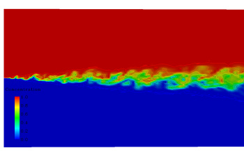
OK, so between airflows with different properties (especially different speed) there is a layer where both airflows mix to create a different one with average properties (saying average is a simplification), the mix in a region called "mixing layer". Unfourtunately, in typical engines, the way both layers mix is turbulent. Here is a typical image of a simulation of a mixing layer.

This turbulent mixing creates sound. Actually is easy to see a similar phenomena in a flute. If you open it, you can see that when you blow you are introducing air that reaches a cavity where sound is produced (actually, there is another phenomenon, resonance, but I would like to illustrate that turbulence creates sound). Another example is when you wave a sharped object in air (like a blade); if you do it quickly enough, you will hear a sound.
That exact phenomenon happens around engines, but the sound is louder. Why? Because the difference between speeds is really high. A glider seems silent although the wings act as blades... but the difference in speed is not so high.
So, what we know now is that the smaller the difference, the smaller the turbulence, the quieter the sound. Those chevrons you see in Boeing 787 actually have that objective. They are actually creating another layer of fluid at a intermediate speed between the air passing the external part of the engine (fan secondary flow) and the external flow, so that the jump of properties is smaller, turbulence gets reduced and sound is quieter.
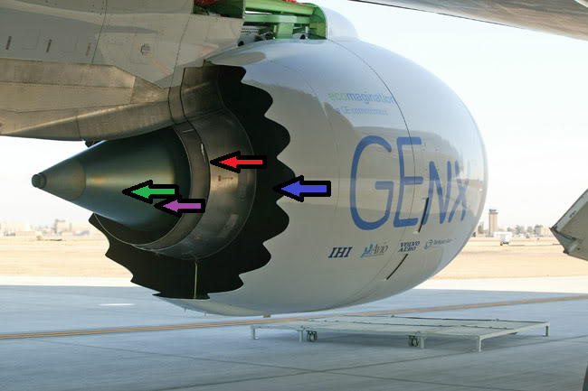
So, to show you the flows in an engine I took your photo and introduced some arrows:

Basically, the blue air coming for the external part of the nacelle mixes with the air coming from the fan (red arrow). Having the chevrons means that some parts are mixed earlier than others, creating positive distortion in the mixing layer like "creating a third flow". The green arrow shows the air from the engine core, but there is another air flow between engine core and the fan, the violet arrow.
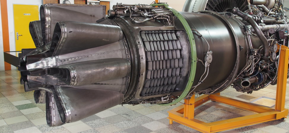
What is shown in the previous answers for Conway and JTD-8 engines are devices using the same principle, but they are actually not the same. In previous jet engines there was not a big secondary flow from the fan as nowadays and the mixture was directly between engine core and external flow, so it is the same principle, but the huge difference between speeds created the need of a more aggressive mixture. This device is called hush kit.
Finally to answer your question, there is no aerodynamic benefit; there is a penalty. The benefit is aeroacoustic.
There is an indirect benefit, though: The amount of acoustic damping material needed to get the cabin quiet enough is reduced. That saves weight, and therefore fuel.
Actually, there were similar tricks used on Boeing aircraft before to reduce jet noise.
The Rolls-Royce Conway (as used on the Boeing 707) had a scalloped exhaust which improved jet mixing and reduced exhaust noise. Since the Conway was also the first operational bypass engine, the lower exhaust speed of this design helped to reduce noise already. At the time of development the engineers expected the engine to be installed in wing roots, and the bypass ratio was only 0.25, however.

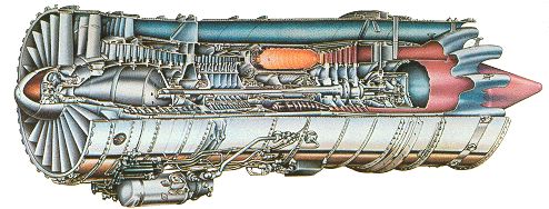
Also the JTD-8 of the Boeing 737-100 used a similar silencer design:

In all cases, the idea is to increase the surface between the hot, fast exhaust gas and the ambient air and to stretch out the noise-intensive mixing process.
See also this question for more information.
The main purpose of the chevrons in the engines is to reduce the engine noise.
Most of the civil airliners use high bypass turbofan engines, which produce significant amount of noise especially at high thrust conditions. Aircraft (engine) noise is especially critical during the takeoff and approach phases as it affects the people in the area around the airport and also the ground crew. Reduction of jet noise has been one of the focus areas of civil aircraft manufacturers since the (failed) SST program.
Source: adg.stanford.edu
As can be seen, the engine noise is perhaps the most important contributer for the total aircraft noise.Thus reduction of engine noise becomes paramount. Most of the high bypass turbofan engines have two flow regions- the central core and the surrounding fan. These regions normally don't mix with each other in the short nozzle.
"Airbus Lagardère - GP7200 engine MSN108 (1)" by Dr Brains - Own work. Licensed under CC0 via Commons.
The schematic below shows the operation a typical high bypass turbofan engines used in civil airliners.
"Turbofan operation" by K. Aainsqatsi - Own work. Licensed under CC BY 2.5 via Commons.
Usually, high bypass ratios reduce noise. The main source of the jet noise is the turbulent mixing of the shear layers in the engine exhaust. These shear layers contain instabilities that lead to highly turbulent vortices that generate the pressure fluctuations responsible for sound.
[2012, V. Parezanovic] Source: http://www.berndnoack.com/
One of the was to reduce noise is to mix the core and bypass gases effectively. NASA carried out research in this area and evaluated a number of different configurations.
Source: NASA- Innovations in Aeronautics
These studies revealed that though the lobed mixers reduced noise better, the associated thrust loss was more and the chevrons offered the optimal solution. Two solutions, tabbed and chevrons were then (simulated flight) tested in various configurations.
These test showed that the configuration with chevrons in fan nozzles only caused the least reduction in thrust coefficient. This probably was the reason this was selected.
In addition to this, research was carried out in developing systems which would optimize the chevron 'immersion' into the jet flow based on the flight condition. Shape memory alloys activated by heat were developed which would allow for full chevron immersion in jet flow during high thrust requirements (for e.g. during takeoff) and not immersing it during cruise where the thrust efficiency is of greater importance.
Variable geometry chevrons for immersion control (AIAA 2006-2546) (Boeing image)