2
$\begingroup$

I am working on designing a remote-controlled flying-wing aircraft and am learning about important configurations and factors in the design.

I have been going through this page because it seems like a pretty useful resource, and I have seen it referenced a few times in other posts. Upon going through it, however, I ran into something which has generated a question about the moment generated by an airfoil, and I believe it relates to my understanding of the aerodynamic centre.

For a given airfoil, I know that, as the angle of attack changes, the center of pressure shifts along the chord line. I also know that (within an operating range avoiding stall nonlinearities) the magnitude of the lift force that acts at the center of pressure increases too.

This leads to my current understanding of the aerodynamic center. If you pick an arbitrary point along the airfoil's chord and calculate the moment generated by this lift force, it will likely change as the angle of attack changes because both the moment arm (distance between an arbitrary point and center of pressure) and magnitude of the force change. The aerodynamic center is, therefore, the point at which the moment does not change with respect to the angle of attack.

My confusion then comes from the diagrams shown on the provided website and elsewhere indicating that the lift can be said to act at the aerodynamic center. I can accept this fact generally, but I am therefore confused about how we can say that it also generates a moment about this point. This is particularly relevant to the website I showed above: how can there be a moment generated by the lift force about the center of mass while also being a moment generated at the aerodynamic center? My understanding is that this moment about the aerodynamic center IS generated by the lift force.

I apologize for making this post so long for what is likely a simple question, but I wanted to explain my current thinking so that hopefully someone can point out the error in my reasoning. Any help would be greatly appreciated.

$\endgroup$
2
  • $\begingroup$ software documentation link and program to accompany link You can create a reflexed airfoil, change angle of attack, see what happens to flow over the airfoil, examine changes in lift and pitching moment. $\endgroup$ Commented Sep 5 at 3:54
  • $\begingroup$ When all else fails, try a delta wing. Think about it. $\endgroup$ Commented Sep 6 at 17:33

3 Answers 3

3
$\begingroup$

Maybe I should have a word with Martin Hepperle, but the way he displays the force is how you will find it in the literature, too.

Please note that in addition to the lift vector at the neutral point, he also displays a moment (symbolized by a circular arrow), and together the varying force and the constant moment are physically correct to describe the full lift forces.

To avoid more confusion about the center of pressure and the neutral point, here are the main aspects:

  • The neutral point / aerodynamic center is fixed over angle of attack
  • All lift forces can be summed up in one force acting at the neutral point plus one moment which is constant over angle of attack.
  • The center of pressure / center of lift is the resulting point at which the summed up lift forces act.
  • The center of pressure changes with angle of attack for cambered airfoils.
$\endgroup$
3
  • $\begingroup$ Thanks for your response, that was my understanding from the diagrams and I appreciate your clarifications. I have a follow up question however: is constant moment an artifact of assuming that the lift force always acts at the aerodynamic center? I am otherwise confused about how a moment would be generated that would be different than simply the effect of the lift force about the true center of mass of the aircraft. $\endgroup$
    – Toogoodoo
    Commented Sep 5 at 18:18
  • 1
    $\begingroup$ @Toogoodoo Follow the link in the third bullet point. If that does not help, please post a new question and describe precisely what is so confusing. Answering in comments leaves little space for explaining broad questions. $\endgroup$ Commented Sep 5 at 22:03
  • $\begingroup$ the link answered my question exactly, thank you! $\endgroup$
    – Toogoodoo
    Commented Sep 6 at 18:32
0
$\begingroup$

Here there's the usual misunderstanding of trimming vs. stability at work.

An airplane is trimmed if all moments (and forces) acting on it sum up to zero. That's simple. Anyway it is stable if: when, for any reason, the AoA increases then the moments decrease in order to consequently decrease the AoA and bring the airplane back to its trimmed position. So, to be stable, an increase in AoA must be counterbalanced by a decrease in moments, so that their ratio is negative.


For a flying airfoil/wing the math is easy since we only have:

  1. the mass acting in the CG
  2. the lift acting at the aerodynamic center (aka ¼ of the chord for thin airfoils at subsonic speed) and
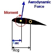
  3. the aerodynamic moment:

enter image description here

(ubiquitous picture by NASA modified by me)

The total pitching moment $M$ in respect to the CG is therefore:

$M=L(x_{cg}-x_{ac})+M_{wing}$

and if we set it to $0$ we get the conditions for trimming. Instead, the stability equation is:

$\frac{∆C_M}{∆\alpha}=\frac{∆C_L}{∆\alpha}(x_{cg}-x_{ac})$

and if we set it to $<0$ we get the condition for stability. $∆$ here is simply the mathematical symbol for "variation". Note that the term $M_{wing}$ has disappeared since its variation in respect to AoA is normally negligible. In order for this equation to be negative, we readily see that $(x_{cg}-x_{ac})$ must be negative i.e. the CG must be in front ($x_{cg}$ smaller) of the AC. This is a general rule valid for any flying airfoil/wing, no matter if it has a "normal" or a reflexed camber.

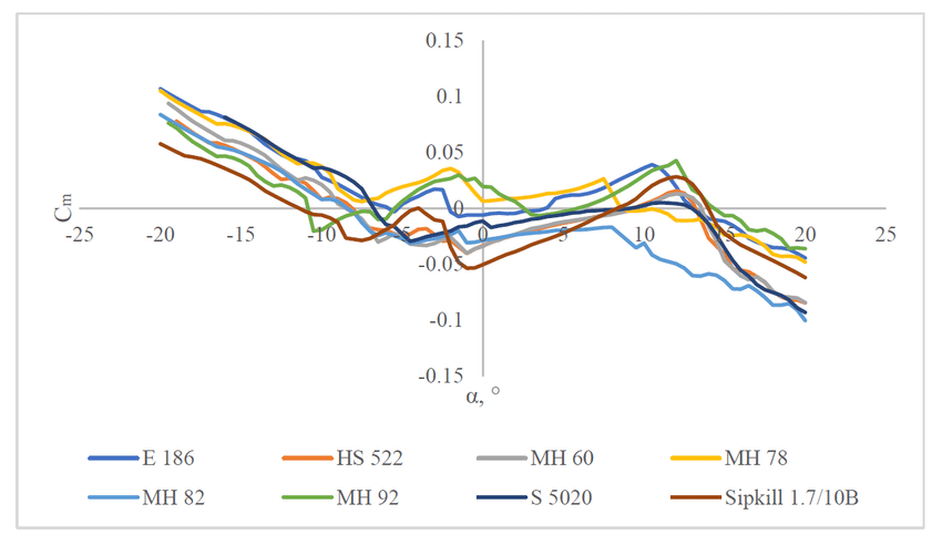
Now to the trim equation: as just seen, the first term $L(x_{cg}-x_{ac})$ is negative in order to make the airplane stable and therefore the second term $M_{wing}$ must necessarily be positive to have a total sum of $0$. And here is where the reflexed camber helps us out: those airfoils normally have a positive moment coefficient, while a "normal" cambered airfoil has a negative moment coefficient:

enter image description here

This plot (source) gives the moment coefficient for several airfoils with more or less reflex: the yellow one would be a good candidate for your flying wing.

$\endgroup$
1
  • $\begingroup$ If lift does not act at CG, how is the aircraft trimmed? What you need in your diagram if another torque in the opposite direction resulting in a net lift (center of pressure) at the CG. $\endgroup$ Commented Sep 6 at 17:32
-1
$\begingroup$

how a moment would be generated that would be different than simply the effect about the true center of mass of the aircraft

Well, it wouldn't be if the center of mass were at the aerodynamic center but ...

  1. Let's not forget what the rest of the aircraft does to the aerodynamic center or "neutral point"

  2. By shifting the center of gravity ahead the neutral point, we can now create the interplay between wing torque and "tail" torque (around the CG) in order to create static stability.

  3. Weight can be moved forward and/or tail lift coefficient and/or area can be increased to increase stability

  4. When this is done, the AC or neutral point moves rearward.

the "neutral point" thus serves as a reference in design, not where actual forces act around unless ... go to beginning of answer.

$\endgroup$
1
  • $\begingroup$ Would the downvoter please explain what is wrong with this answer? $\endgroup$ Commented Sep 6 at 17:28

You must log in to answer this question.

Not the answer you're looking for? Browse other questions tagged .