4
$\begingroup$

In helicopter dynamics the flapping angle and corresponding equation is a well known concept. Suppose now that an hinge is added to the rotor, as with gyrocopters and that there is an aerodynamic moment such that the flapping angle $\beta$ is formed.

In all literature, the centrifugal couple moment is countering the aerodynamic moment. However, why is the centrifugal force not directed radially outward from the blade sense (along $x_{img}$ axis). As this is the new rotary plane where the blade rotates over the $z_{img}$ axis.

My idea is that the centrifugal force is constructed from the rotational vector, and can be calculated in every coordinate system of choice. Therefore, the flap angle analysis can be made in the $x,y,z$ frame. Is this correct?

Moreover, does the use of a centrifugal force in the analysis require me to be in a rotary frame of reference? As my understanding is that this force appears when a transformation from a stationary to a rotary frame is made.

If that is the case, how then would the flapping equation look like when I stay in a stationary frame when there is no centrifugal force?

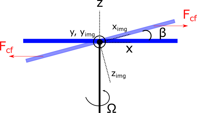
Free body diagram of helicopter rotor with hinge.

$\endgroup$
3
  • $\begingroup$ The centrifugal force is directed radially outward, but in the tip-path plane, itself defined by the combination of the rotating motion and the flapping oscillation. $\endgroup$
    – xxavier
    Commented Nov 19, 2022 at 10:54
  • $\begingroup$ ...and the real axis of rotation is 'blown back' by the flapping oscillation, that real axis being perpendicular to the tip-path plane... $\endgroup$
    – xxavier
    Commented Nov 19, 2022 at 12:41
  • $\begingroup$ I don't get what's wrong with that picture? Centrifugal force is perpendicular with the axis of rotation, just like in the picture $\endgroup$
    – sophit
    Commented Nov 19, 2022 at 15:41

2 Answers 2

1
$\begingroup$

Let me have a go at it. From https://en.wikipedia.org/wiki/Centrifugal_force, "the centrifugal force always points radially outward from the axis of rotation of the rotating frame". This also becomes apperent from the double cross product in $-m\vec{\omega} \times(\vec{\omega}\times \vec{r})$.

Therefore, one is allowed to choose any rotating coordinate system including a rotating coordinate system where the z axis corresponds with the physical rotor axis. The centrifugal force appears as a consequence of going from a stationary to rotating coordinate system. In this coordinate system, the resulting force (vector) is opposing the flap angle $\beta$.

$\endgroup$
1
  • $\begingroup$ You're right, I was assuming rotating already. I edited it $\endgroup$
    – lWindy
    Commented Nov 22, 2022 at 7:45
0
$\begingroup$

why is the centrifugal force not directed radially outward from the blade sense (along $x_{img}$ axis). As this is the new rotary plane where the blade rotates over the $z_{img}$ axis.

The centrifugal force is directed radially outwards from the axis of rotation, as also mentioned in @sophit's comment. But the centrifugal force is only one of the forces that will position the blade rotation plane and blade angle: the flight controls do a good job in tilting the rotation plane for flight path and airspeed control.

Some more explanations in this answer.

$\endgroup$
2
  • $\begingroup$ But is the axis of rotation defined as the physical axis i.e. coupled to the engine, or the imaginary axis which is $z_{img}$ in the figure?. This axis is the axis perpendicular to the tip path plane. $\endgroup$
    – lWindy
    Commented Nov 21, 2022 at 7:18
  • $\begingroup$ If it is the tip path plane, then I do not see why the centrifugal forces counters the blade flap. Namely, there is no arm and therefore no net moment around the $y, y_{img}$ axis. $\endgroup$
    – lWindy
    Commented Nov 21, 2022 at 7:20

You must log in to answer this question.

Not the answer you're looking for? Browse other questions tagged .