I'm unable to find an explanation of gimbal error in a Directional Gyroscope Indicator (DGI) anywhere. Can someone please explain what this is?
1 Answer
Short answer
The gimballing error is the mechanical error introduced by the cardan design of a gyro DI. A cardan joint is linear only when its input and output axes are aligned.
In the gyro DI axes are aligned when the wing is level. When the wing is banked the non linearity of the transmission makes the compass map lead or lag behind the gyro wheel.
Because there is a non linearity, the gyro precession rate is also changed. While the lead/lag error disappears when the wing is level again, the precession rate error is permanent.
Details
There are two main errors on an directional indicator gyro:
- friction drift,
- gimballing error.
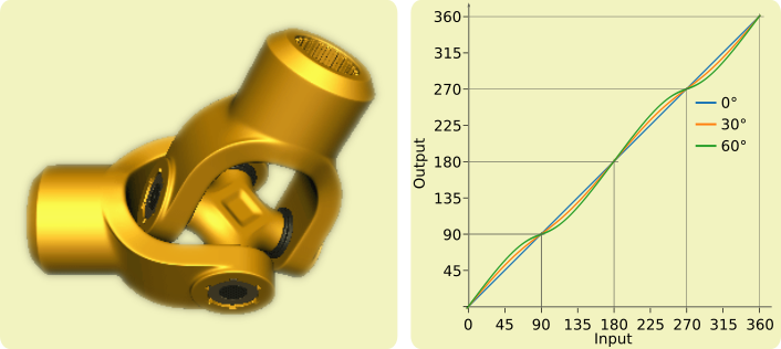
Drift is due to friction occurring in the rotation axis of gimbals. This is analog to drift observed in inertial platforms. Drift is slow and continuous. Gimballing errors occur during large turns at steep angles and are related to the mechanical design of a gyro, which is similar to a cardan joint. In a cardan, input and output velocities are equal when the input and output axes are aligned (0° angle), but differ as soon as there is a misalignment. See this page for a full explanation. The relationship between output and input is this one, computed for a few misalignments:
Non linearity of output vs input in a cardan, left image source, right image adapted from source
We can see the error is null for input angles multiple of 90°. The gimballing error has two aspects.
Recoverable mechanical non linearity
The wheel axis of rotation (not the spining axis) and the output axis are aligned when the aircraft is level. In this case the wheel orientation is exactly transmitted to the map (middle image below).
 Gimballing error when the aircraft is banked. Source for left image
In a turn the outer gimbal axis is banked with the aircraft while the wheel still rotates around a vertical axis (right image above). Because the two gimbal axes are no more aligned, the cardan design introduces an error on the output axis. The compass map starts leading/lagging behind the actual wheel orientation change.
The error can exceed 10°, but is not permanent. It disappears when the aircraft is returned to level flight.
Non recoverable precession error
The cardan non linearity creates accelerations on the wheel. A gyro is sensitive to these accelerations, they perturb its precession rate. A permanent error is introduced in the instrument. A 360° turn may introduce as much as +/-1° error. Fortunately these errors don't have the same sign, and partially cancel the previous ones. I don't have the TSO (C5e) related to DI certification, but I think 1° is a requirement.
More about DI errors.
-
$\begingroup$ thanks this was a good answer. $\endgroup$ Commented Nov 19, 2021 at 11:32
-
1$\begingroup$ I've accepted it. Can you please answer this as well aviation.stackexchange.com/q/90280/35047 $\endgroup$ Commented Nov 19, 2021 at 15:17

