2
$\begingroup$

In many pieces of literature, diagrams as below are shown to explain the directional flight of Helicopter. I have the understanding that the cyclic input will only change the pitch angle of the blades and hence the amount of lift forces acting will vary around the disc. BUT the disc-plane (more specifically, the hub plane), will remain parallel (to the reference plane, for example, the skids, or the top surface of the helicopter). I mean, the disc plane shouldn't pitch down or up as shown in the diagram.

Am I correct? Also, I am finding hard to give a suitable name to the "reference frame", I tried to define above. Is there any standard name for that?

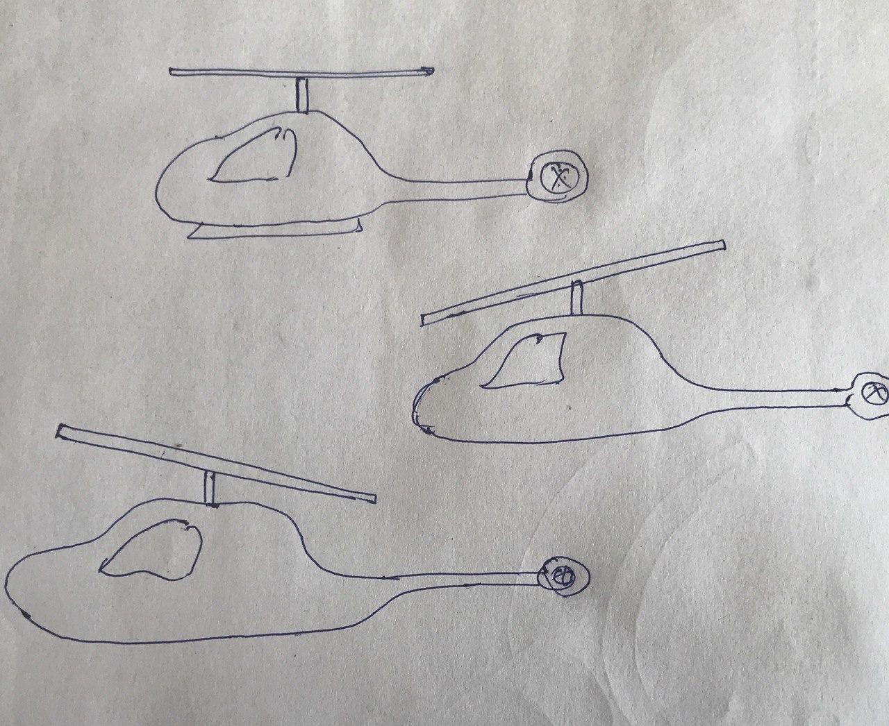
enter image description here

$\endgroup$

2 Answers 2

3
$\begingroup$

The shaft does not tilt, but the disk does.

You understand the function of cyclic control correctly. It indeed changes the pitch of the individual blades, shifting the centre of lift.

However, the blades are not strong enough to take that much bending load. If the rotor was completely stiff, they'd quickly break off. So instead the blades are allowed to flap up and down. That allows the plane of rotation of the blades to change first when you apply cyclic input and the body attitude follows.

The body attitude follows. When the rotor tilts, the action like of lift gets tilted with it, so it no longer passes through the centre of gravity, which will create a moment that will try to pull the body into the attitude corresponding to the rotor. With individual flapping hinges or flexing there is additional, more direct torque on the rotor hub trying to do the same, while on teetering rotor this is the only effect and the way cyclic is rigged prevents the rotor from trying to tilt too far relative to the body.

See also How are pitching and rolling moments transferred from rotor to the body?

$\endgroup$
5
  • $\begingroup$ Thanks. So, I believe what I should have used is - hub plane, instead of a disc plane. Am I correct in understanding that the hub-plane doesn't move (pitch down or up)? $\endgroup$
    – Raj Arjit
    Commented May 20, 2020 at 5:44
  • 1
    $\begingroup$ @RajArjit, the hub indeed does not move. Though on teetering rotors the hub is just a hinge on which the pair of blades teeter—that mechanism is simpler, but it does not transfer any torque to the body, which makes it prone to ‘mast bumping’ when the rotor is unloaded. $\endgroup$
    – Jan Hudec
    Commented May 20, 2020 at 5:47
  • $\begingroup$ thanks. I understand now. $\endgroup$
    – Raj Arjit
    Commented May 20, 2020 at 5:54
  • $\begingroup$ this video suggests that the hub moves by lot. youtube.com/… Please let me know what I am missing. $\endgroup$
    – Raj Arjit
    Commented May 21, 2020 at 8:11
  • $\begingroup$ @RajArjit, the video is so blurry and poor resolution that it does not suggest anything at all. $\endgroup$
    – Jan Hudec
    Commented May 21, 2020 at 15:41
2
$\begingroup$

The blades are hinged near their roots, so they have some degree of freedom, and they flap up and down, so that the disk defined by the path of the blade tips is almost always at an angle with respect to the plane perpendicular to the rotational axle.

$\endgroup$
2
  • $\begingroup$ I understand that. Does the hub always remain at zero angle to the plane perpendicular to the rotational axle? $\endgroup$
    – Raj Arjit
    Commented May 20, 2020 at 5:41
  • $\begingroup$ Raj, the diagrams you have submitted are correct. There is no movement of the main drive shaft other than rotational. The disk (blades) tilts as a result of flapping hinges (flapping occurs whether it’s a fully articulated or rigid rotor head) receiving a control input from the swash plates. The swash plates, one rotating & one non-rotating, turn pilot control inputs into the blade movement which is controllable in any direction. $\endgroup$ Commented May 21, 2020 at 22:06

You must log in to answer this question.

Not the answer you're looking for? Browse other questions tagged .