4
$\begingroup$

I am considering using a 3D printer to make unconventional impellers for a custom-made drone that I am planning to build. I am concerned that these plastic impellers may explode if their motors' RPMs get too high.

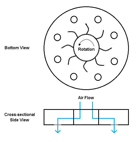
Please see the drawing below.

This drawing is showing two views of an enclosed centrifugal blower impeller with forward curved blades and the bottom plate of the impeller has holes in it. I am thinking that the high static air pressure that will be created within the impeller will generate a good amount of lift for the drone.

This design was inspired after I watched a Youtube video about a drone that uses cross-flow fans for lift:

My concern is that if the motor's RPM gets too high, the static air pressure inside the enclosed impeller will get too high and the impeller will explode, sending plastic shrapnel in all directions.

Because of this explosion risk, would it be advisable that I not use this potentially dangerous impeller?

EDIT

I just want to point out that the blades will be embedded within the enclosed impeller and that the whole impeller is rotated by a motor. The blades will not be part of a separate squirrel cage that will spin within a stationary enclosure that has holes in the bottom of it.

enter image description here

$\endgroup$
1
  • 1
    $\begingroup$ Centrifugal stress will be more of a structural problem than air pressure loads. If it doesn't fall apart, it'll be horribly inefficient at producing thrust. Probably pretty good at making noise though. $\endgroup$ Commented May 19, 2019 at 19:26

2 Answers 2

6
$\begingroup$

I know those things as squirrel cage blowers. As the video says, they are a good choice if you want to move a moderate amount of air without exposing rotating blades.

Impeller, by the way, was initially the word for a sort of airscrew that is moved by the flow. The small thingy in the nose of the Me-163 rocket interceptor was an impeller and needed for driving the plane's electric generator. Unfortunately, this word has recently been abused to mean shrouded propellers.

The proper name for those blowers is "centrifugal fan", and I will continue to use this word for the remainder of this answer.

As @pericynthion says in the comment, air pressure is less of a concern than centrifugal loads. Basically, the blades spin air around and hurl it to the inner housing of the blower, increasing pressure when the kinetic energy of the swirling air is converted to pressure as the air slows down. If we assume that air comes to a total standstill at the housing (which it doesn't, otherwise the blower would choke), the maximum attainable pressure is determined by the radius of the cage $r$ (in meters) and the rotational speed $\omega$ (in rad/sec) of the blades. $$∆p = \rho\cdot r\cdot\frac{\omega^2}{2}$$ For a 20 cm blower spinning at 3000 RPM this would be 5.9 bar. The centrifugal acceleration $a$ on the blade would be $$a = r\cdot\omega^2$$ which produces 1000 g with the same parameters.

To give you an idea about the efficiency: It is generally desirable to accelerate a large volume of air a bit rather than to accelerate a small amount of air by a lot. Therefore, helicopters use the largest practical rotor diameter, so they can capture as much air as possible for lift creation. Centrifugal fans cannot enjoy the same luxury and can only use the air which enters them from the side. As you can see from the two formulas above, your ideal centrifugal fan runs at a low speed but has a large diameter for the best ratio of pressure over centrifugal loads.

If you build them without regards to the loads, yes, those centrifugal fans can indeed be dangerous.

$\endgroup$
11
  • 1
    $\begingroup$ @HRIATEXP Note that the 5.9 bar are the upper limit for the possible pressure. Losses and a non-zero exit speed mean the real value is lower. $\endgroup$ Commented May 20, 2019 at 4:29
  • 1
    $\begingroup$ @HRIATEXP "Works at low efficiency" is not the same as "doesn't work". Depending on the weight of your UAV, this could definitely work. But it's not going to work as well as a propeller. So if you're just doing this to have fun and experiment, by all means, knock yourself out. But if you're trying to make something practical, you'd probably be better served by using a standard propeller (unless there's some other reason why you're avoiding propellers). Just make sure to stand well away the first time you go to max power. $\endgroup$ Commented May 20, 2019 at 5:46
  • 1
    $\begingroup$ Impeller, initially a sort of airscrew that is moved by the flow? Do you have any source for that claim? Etymologically it sounds very wrong. $\endgroup$
    – bogl
    Commented May 20, 2019 at 7:13
  • 1
    $\begingroup$ @bogl: Start from latin: impellere means to drive into (passively) whereas propellere means to drive forward (actively). $\endgroup$ Commented May 20, 2019 at 11:29
  • 1
    $\begingroup$ @HRIATEXP: You could increase the RPM of a propeller just as easily as increasing the RPM of an impeller. $\endgroup$ Commented May 20, 2019 at 14:49
3
$\begingroup$

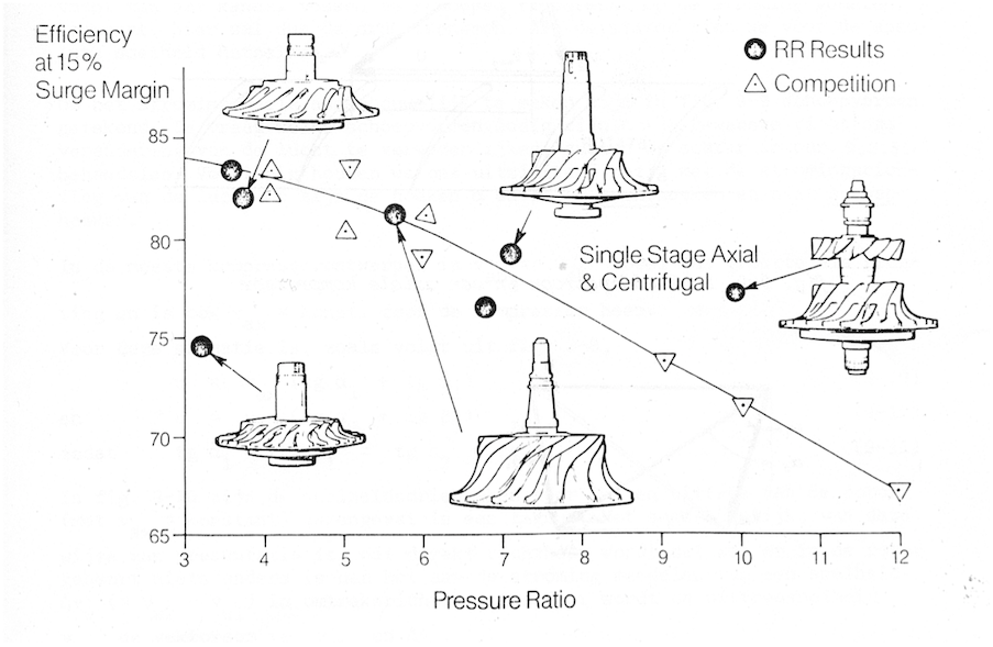
RR publication from the 80s, reproduced in a uni book

Centrifugal stress on the disk is indeed the most pressing issue. Real life centrifugal compressors can get to a compression ration of about 4.2 for a simple single stage fan, at disk tip speeds of 450 m/s which is the maximum for high tensile steel.

Exit speed at the disk tip is often supersonic and needs to be reduced to about 100 m/s, resulting in the total exhaust pressure ratio of 4.2. About half of this is reached at the disk tip. I don't reckon that the design in the OP would even reach a pressure ratio of 2.

Also, air pressure is a less efficient way of propulsion than air velocity. Simply let the pressurised air expand to environment pressure through a properly shaped exhaust.

Industrial centrifugal fans work with pressures measured in kPA, up to a max of around 15, so the exhaust pressure ratio = 1.15 which would not cause much of an explosion danger.

So: no, it would not be a dangerous impeller to use for a drone, provided that the tip speed is low enough for the construction material. Note that a proper design allows for an easy inflow and outflow of air, the air path in the OP drawing has right angles which cause flow restriction and turbulence.

$\endgroup$
2
  • $\begingroup$ @ Koyovis, my impeller design is a very basic one, the impellers you have proposed would of course work much better, but I don't believe I would be able to create one of those with a 3D printer. Also, I am now thinking that an explosion risk could be averted by incorporating a pressure-relief valve somewhere on the housing of the rotating impeller, but this brings up an issue with properly balancing the rotating impeller and it makes me wonder if its worth it. $\endgroup$
    – user36220
    Commented May 20, 2019 at 12:59
  • 1
    $\begingroup$ Just let all the pressure release permanently - you want to create airflow, not air pressure. Yeah the compressors in the picture are the fancy jet engine ones, you won't be needing those. Two disks, straight blades, leave an opening in the centre for air to flow in, create a flow outlet, and Bob is your uncle. $\endgroup$
    – Koyovis
    Commented May 20, 2019 at 13:21

You must log in to answer this question.