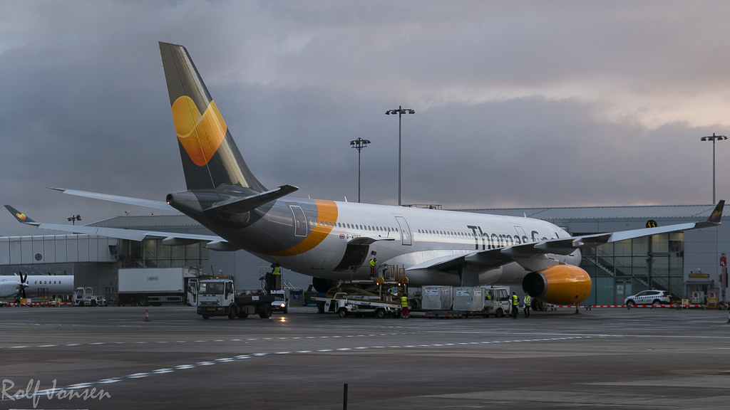
 just wondering what the purpose of the pronounced twist on the Airbus A330 wing root is, I've noticed this on the 380 as well.
-
3$\begingroup$ What do you mean with twist on the wing root? The wing is twisted along its span to improve stall behaviour; that is used on all swept wings. But mentioning wing roots specifically suggests you might mean something else. $\endgroup$– Jan HudecCommented Sep 22, 2017 at 19:40
-
2$\begingroup$ He/she probably used the term incorrectly; the twist in this case is most significant around the root, and is uniform along the rest of the wing rather than consistent across the whole section. $\endgroup$– JihyunCommented Feb 18, 2019 at 7:21
1 Answer
Short answer:
To create a funnel for all the air streaming towards the fuselage.
Slightly longer answer:
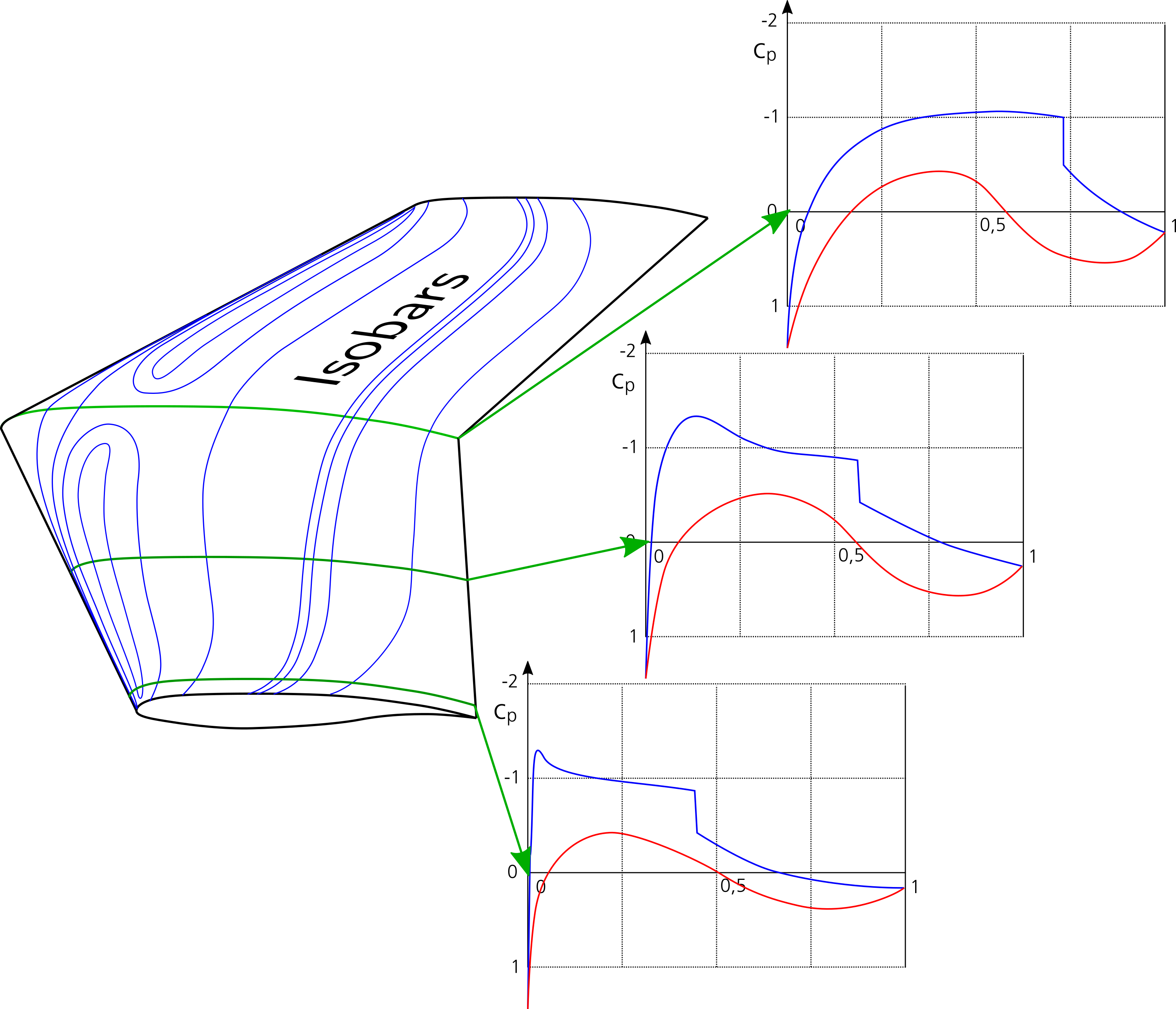
Air approaching a swept wing will be accelerated towards the area with the lowest pressure and, therefore, will be sucked towards the wing's center. The center itself will show a markedly different pressure distribution over chord than the two-dimensional flow over the same airfoil would because here the acceleration is much lower while the deceleration length at the end of the airfoil is compressed. If the swept wing has no twist and the same airfoil over span, a flow pattern similar to that pictured below will result:

The blue lines on the wing surface are lines of equal pressure (isobars) and in the plots denote the pressure coefficient on the upper side of the wing section. The red lines show the pressure coefficient on the lower side.
In order to maximize the achievable lift at transsonic speed it is desirable to modify this wing such that the isobars will run along lines of equal chord percentage over the full span. To achieve this, several tricks must be combined:
- Make the root airfoil thicker at the front and thinner at the rear part.
- Do the reverse for the tip airfoil: It must be made thinner at the front and thicker at the rear part.
- Use negative camber at the wing root.
- In order to compensate for the much higher zero-lift angle of attack of the modified root airfoil, increase its incidence.
The last step is what causes the kink in the trailing edge. Of course, increasing the wing chord at the center increases this effect. In case of the A330 and A340, the incidence changes from +4.5° at the root to 0° between 30% and 70% span and -2° at the tip when on the ground and -2° at 70% span and -5° at the tip in flight.
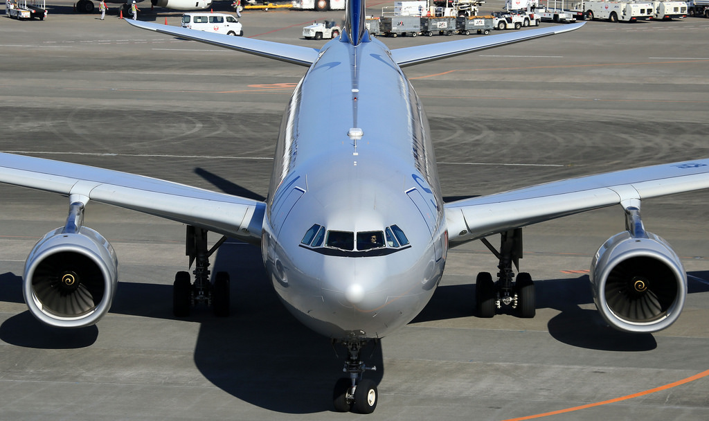
Thanks to @ymb1 who found a very illustrative picture of the A330 (shown below, source) the root twist becomes obvious: The root airfoil has visibly much less forward camber (negative camber, actually) and, consequently, a higher zero-lift angle. In order to produce a similar lift coefficient, the center wing needs a higher incidence to compensate for this change in airfoil shape.
Another find by @ymb1 is this picture of Airbus root airfoils (source). The thick nose is easy to spot; it is needed to shift the suction area on the swept wing root forward so that the pressure distribution becomes more similar to the one of the airfoil at mid-span. Also, while the top has a long straight stretch, the bottom is rounded which in combination produces negative camber. The rounded bottom helps to maximize relative thickness. Since the chord at the center wing is increased, the local lift coefficient can be smaller than on the mid and outer wing and still carry the same circulation for low induced drag. What is saved in lift is added in thickness for structural efficiency and for stowing the landing gear. The lack of rear loading (= high local camber in the rear airfoil section) helps to gain the needed volume for the landing gear bays.
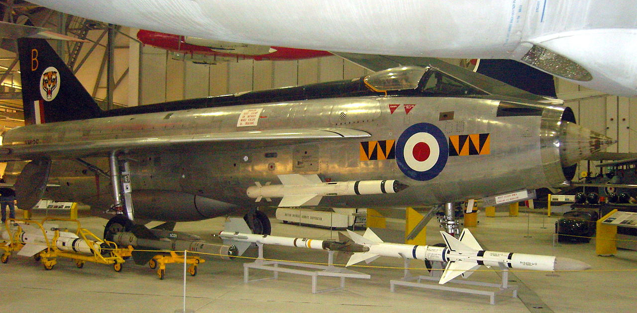
Here is another one, this time an English Electric Lightning F.1. The reflections on the leading edge show nicely how it is pulled down at the root with plenty of nose camber there. This being a design from the early Fifties, this nose camber is used to give the wing better stall behavior and isobar shaping was not yet practised. Note that the local incidence has not been increased at the root.
EE Lightning F.1, Imperial War Museum, Duxford (Edited), CC BY-SA 2.0 (picture by Roland Turner from Birmingham, Great Britain; source)
-
$\begingroup$ Re: negative camber, here's a real nice Airbus poster (source). I'm sure you'll find good use for the different profiles/designs for the answer. $\endgroup$– user14897Commented Feb 20, 2019 at 17:10
-
$\begingroup$ @ymb1: Thank you for the contribution! $\endgroup$ Commented Feb 20, 2019 at 21:06
-
$\begingroup$ @PeterKämpf: question: what does blue and red line in your plot mean? I am really hoping blue line is the air speed, if that's the case the sudden drop in the blue line suggest the sudden drop in speed and sudden increase in pressure, that's where the normal shock wave and separation will be. I REALLY need some confirmation on this $\endgroup$– eliuCommented May 29, 2021 at 14:34
-
$\begingroup$ @eliu: You are right, I should had explained that. Red is the lower side pressure coefficient and blue the upper side pressure coefficient. For pressure coefficient please read this answer. $\endgroup$ Commented May 29, 2021 at 16:34
-
1$\begingroup$ @eliu No, not back to square one. The pressure coefficient is inversely proportional to the square of speed. Note the inverse y axis: A rising line means accelerated flow. $\endgroup$ Commented May 29, 2021 at 16:45


