Why aren't ducted rotors used in gas turbines?
They are. There are actually two ducts forming an annular channel, as blades and vanes do not extend down to the rotating shaft. As air is more and more compressed, it takes less space, hence the channel area decrease continuously along the path.
These specific points:
I thought that a number of reasons would seem to justify such a solution:
- Improved centrifugal resistance, especially if some sort of bearing system (hydraulic/electromagnetic maybe) is included around the duct
- Higher blades bending stiffness, and thus reduced blade vibration
- Better tip leakage retention
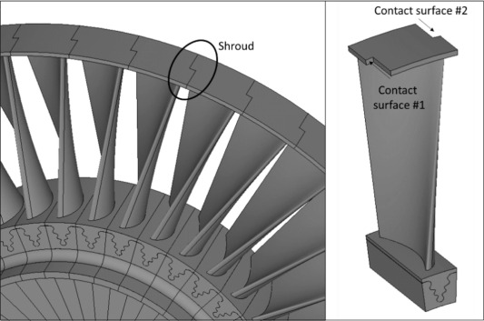
are linked to the use of shrouded blades. An answer already exists: Why do turbine rotors have an outer shroud but compressors don't?.
I'm answering only about how ducting is made, from an air-tightness standpoint.
A gas turbine engine includes a compressor to feed the engine in air, a combustor to burn fuel with air, and a turbine to spin the compressor.
Compressor and turbine are made of successive stages, each stage having fixed vanes (stator assembly) and rotating blades (rotor assembly). Vanes in a compressor stage follow blades and are divergent, in order to convert the excess of velocity created by the blades into static pressure. This is the opposite in a turbine stage, they come first to convert pressure into velocity to rotate the blades behind.
Compressor and turbine are ducted, though the ducts are made of several sections. The ducting of the turbine is more complex.
Compressor
Stators and rotors are assembled in a way which creates two ducts:
A rotating inner duct holds the rotor blades. It has tracks on which the inner tips of the stator vanes slide. These tracks are usually labyrinth seals to prevent air from bypassing the vanes.
A fixed outer duct holds the stator vanes. It has tracks on which the outer tips fo the rotor blades slide. This time the tracks are flat, made of abradable material in order to fit the length of the blades. The first stators have vanes which can rotate along their radial axis in order to adjust the angle of attack and keep the engine in optimal working conditions.
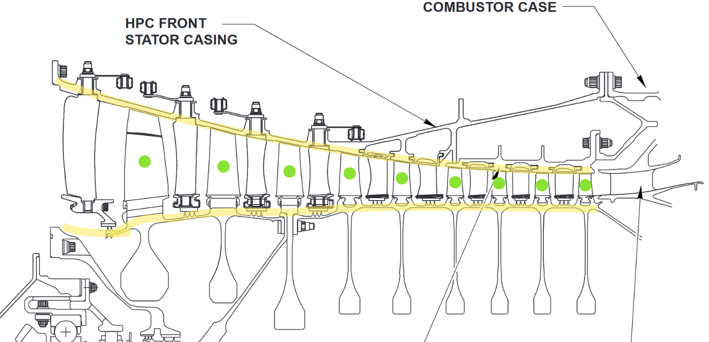
This is the high-pressure compressor from a CMF56-7B (Boeing 737 NG):

Source: Airbus engine training manual.
You can see yellow-higlighed the two walls of the annular duct. Rotating blades are marked with green dots. This duct is air-tight enough for the compressor function. However a lot of air leaves it without going to the combustor: Bleed air tapped in the cavity you see on the right, air used for engine cooling, etc.
The high-pressure turbine spins the inner drum, and the outer casing is fixed to the fan frame which is a mounting point of the engine, fixed to the wing.
Turbine
Turbines are working at high temperature, because a combustor generating a higher temperature gas increases the engine efficiency. The consequence is turbine blades and vanes work near their limits in term of temperature, as well as the outer wall of the ducting.
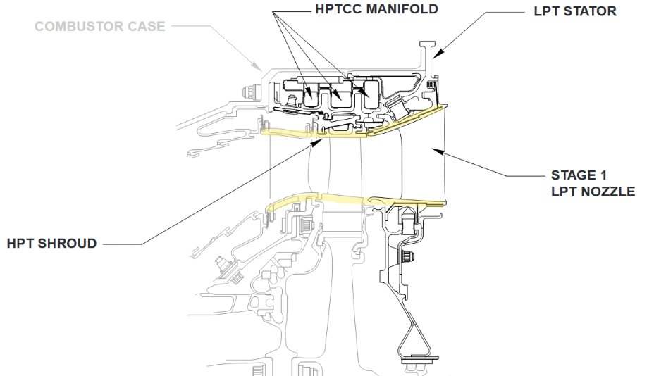
The ducting is therefore designed to help cool the turbine, leading to a more complex assembly, with holes for cooling air. It must also adapt to a higher dilatation. The shroud at this level is composed of individual segments which can move (HPTCC below), rather than simply using an abradable material.
The high-pressure turbine for the same engine:


