Simplified and shortened
Source Link
mins
  • 80.8k
  • 30
  • 326
  • 473

What does the actual path of air withinflow in a turbojet engine look like? Axial or helical?

While Wikipedia describes the flow path as axial, I wonder if the path could be helical instead. Wikipedia explanation is described first in section 1, section 4 is for what could be the actual flow path, and sections 2 and 3 list the reasons for that. Section 5 is my question.


1. Usual high-level explanation

Wikipedia explains air flow in a jet engine this simplified way:
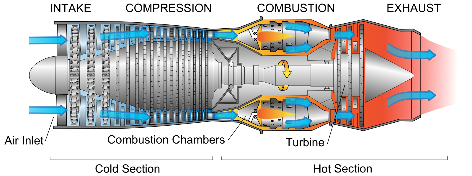
enter image description here
Flow path, Wikipedia, author: Jeff Dahl

Not obvious on the picture, there is a stator with vanes after each rotor, to create the pressure increase on vanes pressure side, and to straighten the flow for the next stage of the cascade, else there would be no compression and the engine would be an expensive fan. See this question for a picture showing the stators.


2. Taking into account blade and vanes

Usual depiction of the path, taking into account blades and vanes, is zigzagging, similar to:

enter image description here

The(Flow path above seems valid for motionless blades and vanes, ignoring blades are in rotational motion. If we dive into a bit more detailed explanationWikipedia, the path would be refined like thisauthor:

enter image description here

Vanes pressure side is upward while blades pressure side is downward.


3. Taking into account blade rotation Jeff Dahl)

With blades rotation, blades of the second stage do move while air is traveling across the first stage. While rotating, second stage blades deflect older air, which now exits the second stage using a vane whichThis is lower than the vane it exited the first stage (during this time air of the first stage has reachedway the second stage, butflow is deflected by an upper bladedepicted on many diagrams, etc)however shouldn't the flow be somehow helical:

enter image description hereenter image description here

Air path is therefore spiraled a bit, the exact amount of the helical displacement depending of the ratio between air axial speed and blades angular speed. This is not necessarilyhelical flow seems more accurate when looking at the exact vane angular spacing (or a multipledetails of it).


4. Seemingly more consistent depiction of air path

If this was the correct way it works, then the overall flow would rather be helical than axial, something more like thisacross rotors and stators:

enter image description hereenter image description here


5. Question So my question: How blades and vanes impact overall air path? How the air path can be better explained, taking into account blades are not fixed?

I'm looking for some details, perhaps blade/vanes geometry and airspeed, not an over-simplified view.

What does the actual path of air within a turbojet engine look like?

While Wikipedia describes the flow path as axial, I wonder if the path could be helical instead. Wikipedia explanation is described first in section 1, section 4 is for what could be the actual flow path, and sections 2 and 3 list the reasons for that. Section 5 is my question.


1. Usual high-level explanation

Wikipedia explains air flow in a jet engine this simplified way:

enter image description here
Flow path, Wikipedia, author: Jeff Dahl

Not obvious on the picture, there is a stator with vanes after each rotor, to create the pressure increase on vanes pressure side, and to straighten the flow for the next stage of the cascade, else there would be no compression and the engine would be an expensive fan. See this question for a picture showing the stators.


2. Taking into account blade and vanes

Usual depiction of the path, taking into account blades and vanes, is zigzagging, similar to:

enter image description here

The path above seems valid for motionless blades and vanes, ignoring blades are in rotational motion. If we dive into a bit more detailed explanation, the path would be refined like this:

enter image description here

Vanes pressure side is upward while blades pressure side is downward.


3. Taking into account blade rotation

With blades rotation, blades of the second stage do move while air is traveling across the first stage. While rotating, second stage blades deflect older air, which now exits the second stage using a vane which is lower than the vane it exited the first stage (during this time air of the first stage has reached the second stage, but is deflected by an upper blade, etc):

enter image description here

Air path is therefore spiraled a bit, the exact amount of the helical displacement depending of the ratio between air axial speed and blades angular speed. This is not necessarily the exact vane angular spacing (or a multiple of it).


4. Seemingly more consistent depiction of air path

If this was the correct way it works, then the overall flow would rather be helical than axial, something more like this:

enter image description here


5. Question: How blades and vanes impact overall air path? How the air path can be better explained, taking into account blades are not fixed?

I'm looking for some details, perhaps blade/vanes geometry and airspeed, not an over-simplified view.

What does the actual air flow in a turbojet engine look like? Axial or helical?

Wikipedia describes the flow path as axial:

enter image description here

(Flow path, Wikipedia, author: Jeff Dahl)

This is the way the flow is depicted on many diagrams, however shouldn't the flow be somehow helical:

enter image description here

This helical flow seems more accurate when looking at the details of the flow across rotors and stators:

enter image description here


So my question: How blades and vanes impact the air path?

replaced http://aviation.stackexchange.com/ with https://aviation.stackexchange.com/
Source Link

While Wikipedia describes the flow path as axial, I wonder if the path could be helical instead. Wikipedia explanation is described first in section 1, section 4 is for what could be the actual flow path, and sections 2 and 3 list the reasons for that. Section 5 is my question.


1. Usual high-level explanation

Wikipedia explains air flow in a jet engine this simplified way:

enter image description here
Flow path, Wikipedia, author: Jeff Dahl

Not obvious on the picture, there is a stator with vanes after each rotor, to create the pressure increase on vanes pressure side, and to straighten the flow for the next stage of the cascade, else there would be no compression and the engine would be an expensive fan. See this questionthis question for a picture showing the stators.


2. Taking into account blade and vanes

Usual depiction of the path, taking into account blades and vanes, is zigzagging, similar to:

enter image description here

The path above seems valid for motionless blades and vanes, ignoring blades are in rotational motion. If we dive into a bit more detailed explanation, the path would be refined like this:

enter image description here

Vanes pressure side is upward while blades pressure side is downward.


3. Taking into account blade rotation

With blades rotation, blades of the second stage do move while air is traveling across the first stage. While rotating, second stage blades deflect older air, which now exits the second stage using a vane which is lower than the vane it exited the first stage (during this time air of the first stage has reached the second stage, but is deflected by an upper blade, etc):

enter image description here

Air path is therefore spiraled a bit, the exact amount of the helical displacement depending of the ratio between air axial speed and blades angular speed. This is not necessarily the exact vane angular spacing (or a multiple of it).


4. Seemingly more consistent depiction of air path

If this was the correct way it works, then the overall flow would rather be helical than axial, something more like this:

enter image description here


5. Question: How blades and vanes impact overall air path? How the air path can be better explained, taking into account blades are not fixed?

I'm looking for some details, perhaps blade/vanes geometry and airspeed, not an over-simplified view.

While Wikipedia describes the flow path as axial, I wonder if the path could be helical instead. Wikipedia explanation is described first in section 1, section 4 is for what could be the actual flow path, and sections 2 and 3 list the reasons for that. Section 5 is my question.


1. Usual high-level explanation

Wikipedia explains air flow in a jet engine this simplified way:

enter image description here
Flow path, Wikipedia, author: Jeff Dahl

Not obvious on the picture, there is a stator with vanes after each rotor, to create the pressure increase on vanes pressure side, and to straighten the flow for the next stage of the cascade, else there would be no compression and the engine would be an expensive fan. See this question for a picture showing the stators.


2. Taking into account blade and vanes

Usual depiction of the path, taking into account blades and vanes, is zigzagging, similar to:

enter image description here

The path above seems valid for motionless blades and vanes, ignoring blades are in rotational motion. If we dive into a bit more detailed explanation, the path would be refined like this:

enter image description here

Vanes pressure side is upward while blades pressure side is downward.


3. Taking into account blade rotation

With blades rotation, blades of the second stage do move while air is traveling across the first stage. While rotating, second stage blades deflect older air, which now exits the second stage using a vane which is lower than the vane it exited the first stage (during this time air of the first stage has reached the second stage, but is deflected by an upper blade, etc):

enter image description here

Air path is therefore spiraled a bit, the exact amount of the helical displacement depending of the ratio between air axial speed and blades angular speed. This is not necessarily the exact vane angular spacing (or a multiple of it).


4. Seemingly more consistent depiction of air path

If this was the correct way it works, then the overall flow would rather be helical than axial, something more like this:

enter image description here


5. Question: How blades and vanes impact overall air path? How the air path can be better explained, taking into account blades are not fixed?

I'm looking for some details, perhaps blade/vanes geometry and airspeed, not an over-simplified view.

Notice removed Authoritative reference needed by mins
Bounty Ended with user14897's answer chosen by mins
Added an introduction
Source Link
mins
  • 80.8k
  • 30
  • 326
  • 473

While Wikipedia describes the flow path as axial, I wonder if the path could be helical instead. Wikipedia explanation is described first in section 1, section 4 is for what could be the actual flow path, and sections 2 and 3 list the reasons for that. Section 5 is my question.


1. Usual high-level explanation

Wikipedia explains air flow in a jet engine this simplified way:

enter image description here
Flow path, Wikipedia, author: Jeff Dahl

Not obvious on the picture, there is a stator with vanes after each rotor, to create the pressure increase on vanes pressure side, and to straighten the flow for the next stage of the cascade, else there would be no compression and the engine would be an expensive fan. See this question for a picture showing the stators.


2. Taking into account blade and vanes

Usual depiction of the path, taking into account blades and vanes, is zigzagging, similar to:

enter image description here

The path above seems valid for motionless blades and vanes, ignoring blades are in rotational motion. If we dive into a bit more detailed explanation, the path would be refined like this:

enter image description here

Vanes pressure side is upward while blades pressure side is downward.


3. Taking into account blade rotation

With blades rotation, blades of the second stage do move while air is traveling across the first stage. While rotating, second stage blades deflect older air, which now exits the second stage using a vane which is lower than the vane it exited the first stage (during this time air of the first stage has reached the second stage, but is deflected by an upper blade, etc):

enter image description here

Air path is therefore spiraled a bit, the exact amount of the helical displacement depending of the ratio between air axial speed and blades angular speed. This is not necessarily the exact vane angular spacing (or a multiple of it).


4. Seemingly more consistent depiction of air path

If this was the correct way it works, then the overall flow would rather be helical than axial, something more like this:

enter image description here


5. Question: How blades and vanes impact overall air path? How the air path can be better explained, taking into account blades are not fixed?

I'm looking for some details, perhaps blade/vanes geometry and airspeed, not an over-simplified view.

While Wikipedia describes the flow path as axial, I wonder if the path could be helical instead. Wikipedia explanation is described first in section 1, section 4 is for what could be the actual flow path, and sections 2 and 3 list the reasons for that. Section 5 is my question.


1. Usual high-level explanation

Wikipedia explains air flow in a jet engine this simplified way:

enter image description here
Flow path, Wikipedia, author: Jeff Dahl

Not obvious on the picture, there is a stator with vanes after each rotor, to create the pressure increase on vanes pressure side, and to straighten the flow for the next stage of the cascade, else there would be no compression and the engine would be an expensive fan. See this question for a picture showing the stators.


2. Taking into account blade and vanes

Usual depiction of the path, taking into account blades and vanes, is zigzagging, similar to:

enter image description here

The path above seems valid for motionless blades and vanes, ignoring blades are in rotational motion. If we dive into a bit more detailed explanation, the path would be refined like this:

enter image description here

Vanes pressure side is upward while blades pressure side is downward.


3. Taking into account blade rotation

With blades rotation, blades of the second stage do move while air is traveling across the first stage. While rotating, second stage blades deflect older air, which now exits the second stage using a vane which is lower than the vane it exited the first stage (during this time air of the first stage has reached the second stage, but is deflected by an upper blade, etc):

enter image description here

Air path is therefore spiraled a bit, the exact amount of the helical displacement depending of the ratio between air axial speed and blades angular speed. This is not necessarily the exact vane angular spacing (or a multiple of it).


4. Seemingly more consistent depiction of air path

If this was the correct way it works, then the overall flow would rather be helical than axial, something more like this:

enter image description here


5. Question: How blades and vanes impact overall air path? How the air path can be better explained, taking into account blades are not fixed?

I'm looking for some details, perhaps blade/vanes geometry and airspeed, not an over-simplified view.

added 300 characters in body
Source Link
mins
  • 80.8k
  • 30
  • 326
  • 473
Loading
added 300 characters in body
Source Link
mins
  • 80.8k
  • 30
  • 326
  • 473
Loading
Notice added Authoritative reference needed by mins
Bounty Started worth 100 reputation by mins
edited body
Source Link
mins
  • 80.8k
  • 30
  • 326
  • 473
Loading
edited body
Source Link
mins
  • 80.8k
  • 30
  • 326
  • 473
Loading
added 156 characters in body
Source Link
mins
  • 80.8k
  • 30
  • 326
  • 473
Loading
added 156 characters in body
Source Link
mins
  • 80.8k
  • 30
  • 326
  • 473
Loading
Changed drawing for spiraling flow
Source Link
mins
  • 80.8k
  • 30
  • 326
  • 473
Loading
Changed drawing for spiraling flow
Source Link
mins
  • 80.8k
  • 30
  • 326
  • 473
Loading
added 7 characters in body
Source Link
mins
  • 80.8k
  • 30
  • 326
  • 473
Loading
edited body
Source Link
mins
  • 80.8k
  • 30
  • 326
  • 473
Loading
Added details to clarify why I think Wikipedia explanation is over simplified, and maybe misleading.
Source Link
mins
  • 80.8k
  • 30
  • 326
  • 473
Loading
added 26 characters in body
Source Link
mins
  • 80.8k
  • 30
  • 326
  • 473
Loading
Tweeted twitter.com/StackAviation/status/797198630922895361
added 336 characters in body
Source Link
mins
  • 80.8k
  • 30
  • 326
  • 473
Loading
Added explicit reference to stator vanes
Source Link
mins
  • 80.8k
  • 30
  • 326
  • 473
Loading
added 19 characters in body
Source Link
DeltaLima
  • 84.5k
  • 11
  • 276
  • 371
Loading
added 45 characters in body
Source Link
mins
  • 80.8k
  • 30
  • 326
  • 473
Loading
added 2 characters in body
Source Link
mins
  • 80.8k
  • 30
  • 326
  • 473
Loading